
Active coke regeneration system and method

A technology of activated coke regeneration and regenerator, which is applied in the field of activated coke regeneration system, can solve the problems of potential safety hazards, low pressure, and high energy consumption for regeneration, and achieves improved safety and economy, simple process flow, and safe and reliable operation. Effect

Inactive Publication Date: 2019-04-26
SINOPEC ENG +1
View PDF7 Cites 1 Cited by
  • Summary
  • Abstract
  • Description
  • Claims
  • Application Information

AI Technical Summary

Problems solved by technology

[0004] The inventor found that the existing regeneration process has the following three disadvantages: (1) Once any tube bundle in the regenerator heating section, desorption section and cooling section is damaged, air or hot flue gas containing excess oxygen will directly contact with high-temperature activated coke , may cause active coke to spontaneously ignite, posing potential safety hazards; (2) high-temperature activated coke is cooled by air in the cooling section of the regenerator, and the hot air is directly discharged into the atmosphere. The air in the cooling section exchanging heat with the active coke, and the hot flue gas in the heating section and desorption section exchanging heat with the active coke are all slightly positive pressure, the pressure is very low, and the heat exchange efficiency is low, so that the regenerator cooling section, heating section and desorption section The required heat exchange area is larger and the equipment is larger

Method used


Image

  • Active coke regeneration system and method
  • Active coke regeneration system and method

Examples


Embodiment Construction

[0025] Preferred embodiments of the present invention will be described in more detail below. Although preferred embodiments of the present invention are described below, it should be understood that the present invention can be embodied in various forms and should not be limited by the embodiments set forth herein.

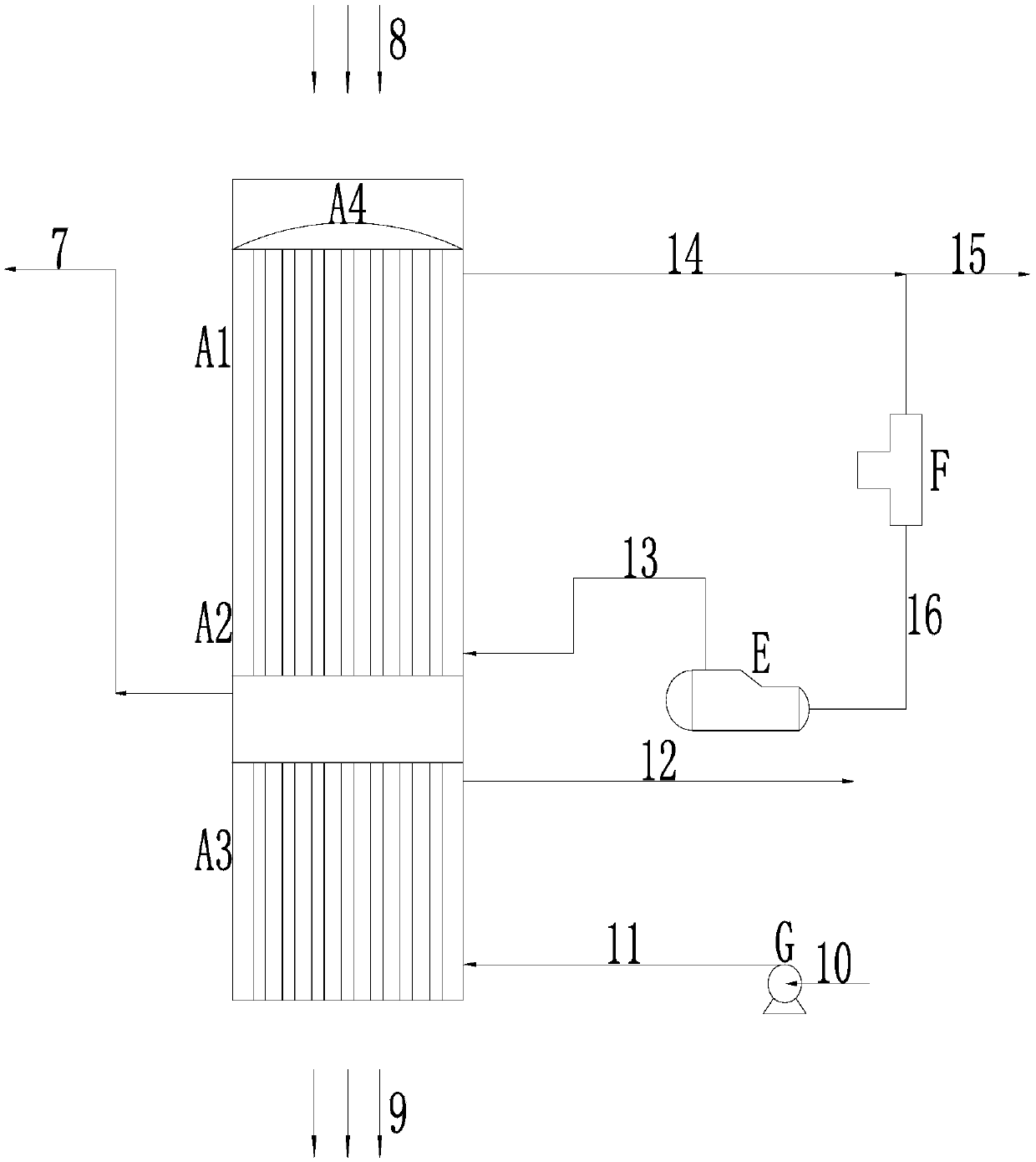
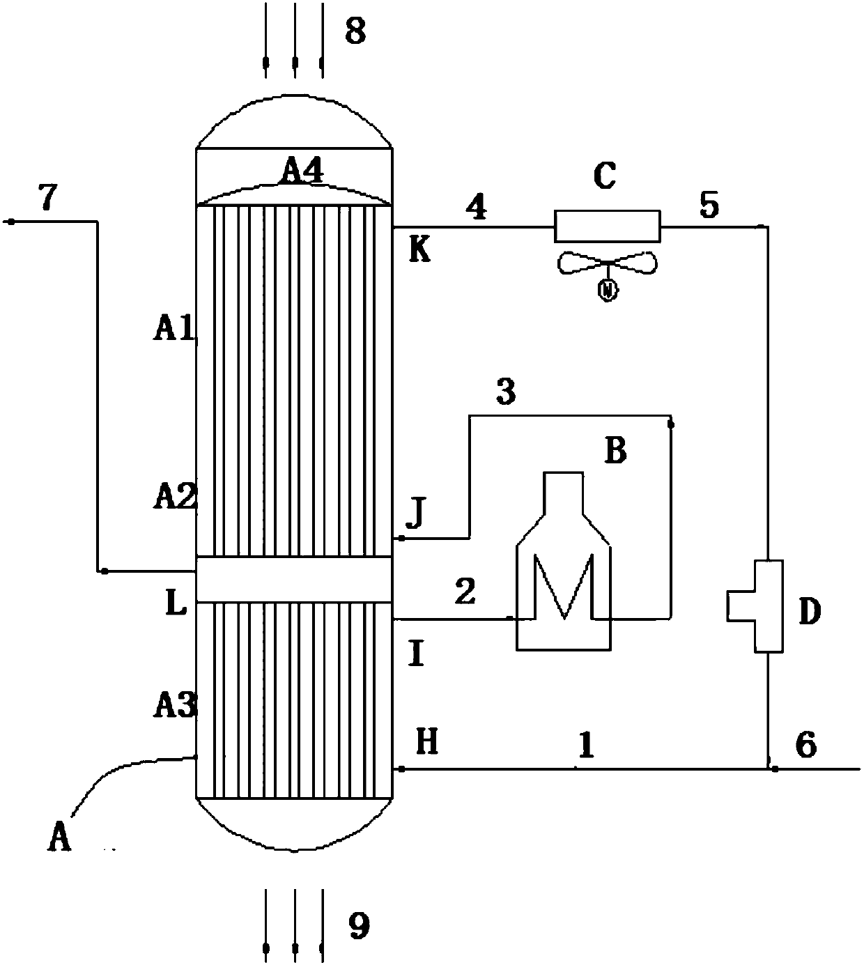
[0026] refer to figure 2 , the active coke regeneration system according to the present invention includes: regenerator A, which is sequentially provided with heating section A1, desorption section A2 and cooling section A3 from top to bottom; the bottom of cooling section A3 is provided with a first nitrogen inlet H, and the top of cooling section A3 A first nitrogen outlet I is provided; a second nitrogen inlet J is provided at the bottom of the desorption section A2; a second nitrogen outlet K is provided at the top of the heating section A1; a heating furnace B is connected to the first nitrogen outlet I of the cooling section A3 and the desorption section A...


PUM


Abstract

The invention belongs to the field of active coke moving reactor dry flue gas desulfurization, and relates to an active coke regeneration system and method. The active coke regeneration system comprises a regenerator, a heating furnace, a cooler and a compressor, wherein a heating section, a desorption section and a cooling section are successively arranged on the regenerator from top to bottom; afirst nitrogen inlet is formed in the bottom of the cooling section, and a first nitrogen outlet is formed in the top of the cooling section; a second nitrogen inlet is formed in the bottom of the desorption section; and a second nitrogen outlet is formed in the top of the heating section; the heating furnace communicates with the first nitrogen outlet of the cooling section and the second nitrogen inlet of the desorption section; the cooler communicates with the second nitrogen outlet of the heating section; the compressor communicates with the cooler and the first nitrogen inlet of the cooling section; and nitrogen passes through the first nitrogen inlet, the cooling section, the first nitrogen outlet, the heating furnace, the second nitrogen inlet, the desorption section, the heating section, the second nitrogen outlet, the cooler, the compressor, and the first nitrogen inlet successively to form a closed nitrogen circulation system. According to the active coke regeneration systemand method, the technological process is simple, operation is safe and reliable, and safety and the economical efficiency of the active coke regeneration process are improved.

Description

technical field [0001] The invention relates to the field of active coke moving bed dry flue gas desulfurization, and more specifically relates to an active coke regeneration system and method. Background technique [0002] The activated coke dry desulfurization process began to be applied industrially in the 1980s. With the increasing environmental protection requirements, activated coke dry desulfurization technology has attracted more and more attention due to its outstanding advantages such as high desulfurization efficiency, no water consumption, no waste water and residue discharge, and equipment corrosion problems. widely. [0003] Typical active coke dry desulfurization includes two parts: adsorption desulfurization and regeneration. The moving bed desulfurization and regeneration process is as follows: the active coke desulfurization tower is a moving bed reactor, and the active coke moves slowly from top to bottom in the reactor to achieve saturated adsorption of ...

Claims


Application Information

Patent Timeline
Patent Type & Authority Applications(China)
IPC IPC(8): B01D53/04
CPCB01D53/0462B01D2257/302
Inventor 黄孟旗吴德飞李出和郝少博周桂娟徐永根
Owner SINOPEC ENG
Learn More