Helicopter rotor wing operating device and rotor wing device

A helicopter rotor and control device technology, applied in the field of unmanned aerial vehicles, can solve the problems of complex swash plate structure, difficult manufacturing and assembly, low control efficiency, etc., achieve stable and efficient output, improve space utilization, and simplify the structure. Effect

Pending Publication Date: 2019-04-26
一飞智控(天津)科技有限公司
View PDF0 Cites 2 Cited by
  • Summary
  • Abstract
  • Description
  • Claims
  • Application Information

AI Technical Summary

Problems solved by technology

[0003] First, small unmanned helicopters are limited by the rotor space, and most of them adopt the off-axis control method, which will cause the disadvantages of complex external structure, large system weight, low force transmission efficiency, etc. Big
[0004] Second, the swash plate of traditional unmanned helicopters with periodic variable pitch has a complex structure, generally composed of universal bearings and other accessories, but it is difficult to

Method used


Image

  • Helicopter rotor wing operating device and rotor wing device
  • Helicopter rotor wing operating device and rotor wing device
  • Helicopter rotor wing operating device and rotor wing device

Examples


Embodiment 1

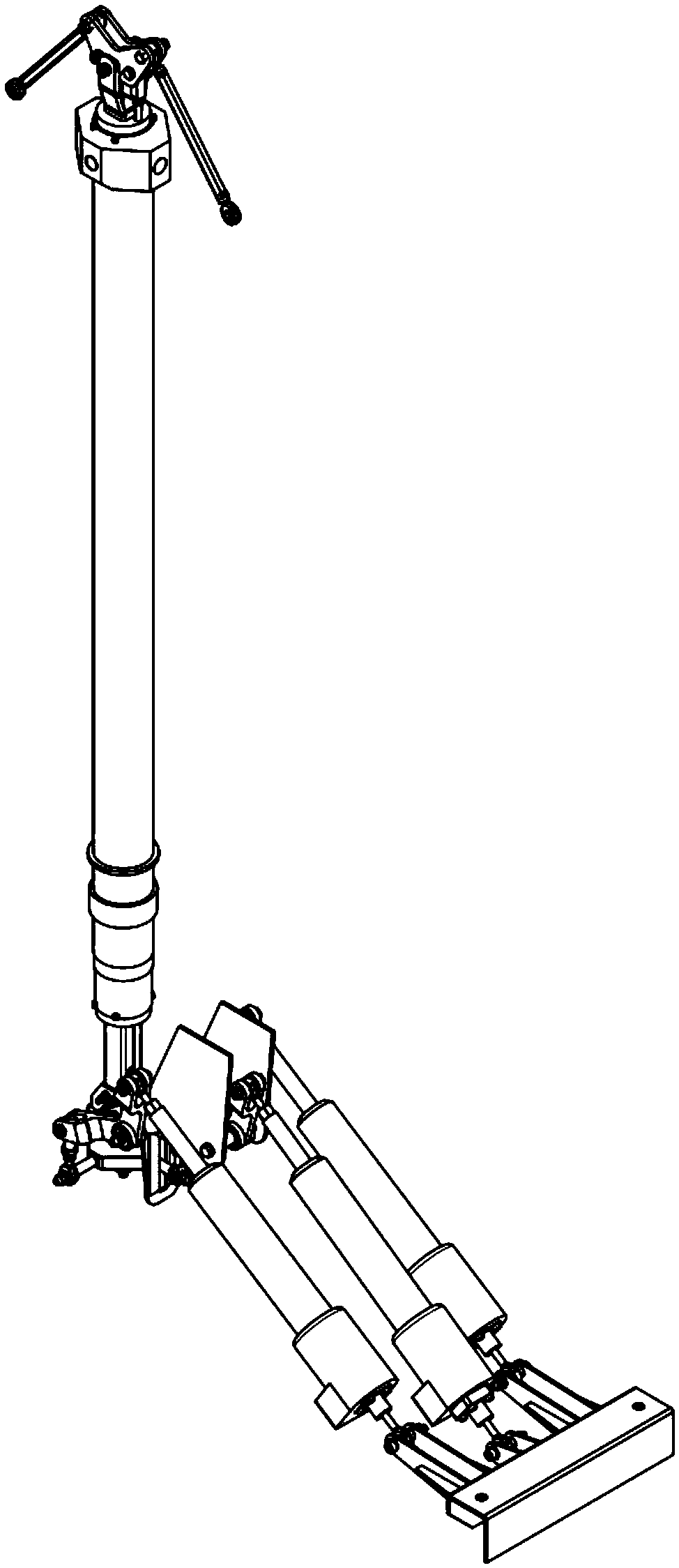
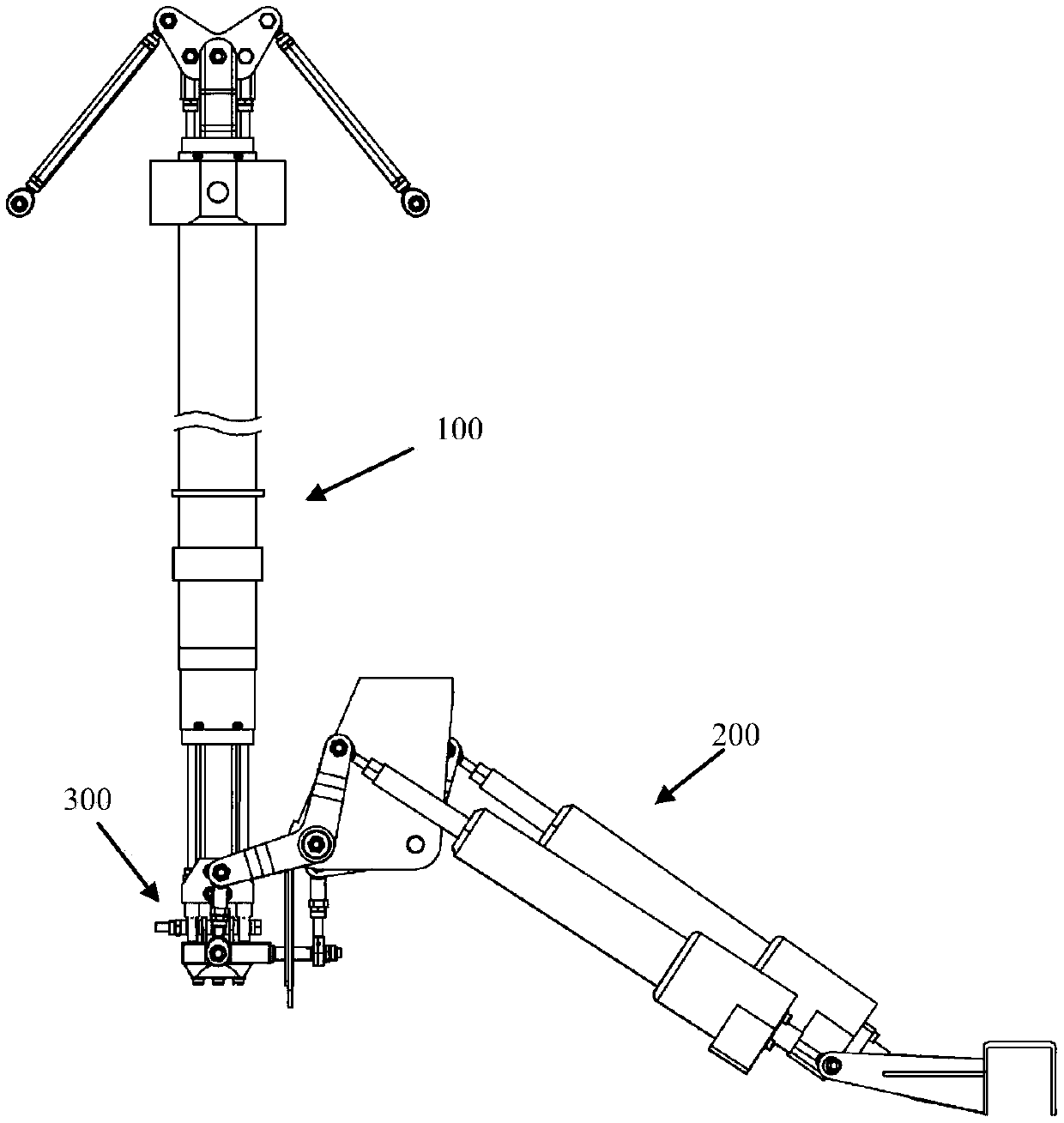
[0034] A kind of helicopter rotor control device of the present invention is characterized in that: comprises steering gear drive assembly 200, swash plate assembly 300 and total moment slider assembly 100,

[0035] The steering gear drive assembly includes three linear steering gears 210 whose tail ends are rotatably connected to the body. The body is rotatably connected to an L-shaped control arm 211;

[0036] The swash plate assembly includes a swash plate 310, a swash plate rotation shaft 311 rotatably set in the swash plate, and the swash plate arm 312, 313, the swash plate support arm is hinged to the other end of the L-shaped control arm through the transmission rod 212;

[0037] The total moment slide bar assembly includes a central joint bearing 111 arranged at the lower end of the total moment slide bar 110, corresponding to a side joint bearing 121 arranged at the lower end of the long tie rod 120, and the balls of the central joint bearing 111 and the side joint b...

Embodiment 2

[0047] As a specific embodiment, the fixed end of the linear steering gear is connected to the body through a joint bearing, and the output end of the linear steering gear is connected to the L-shaped control arm through a joint bearing.

[0048] When installing the fixed end of the linear steering gear, first connect the fixed end of the linear steering gear to the mounting part of the steering gear through bolts, then connect the mounting part of the steering gear to the joint bearing through threads, and finally fix the joint bearing to the installation position of the body with bolts. When installing the output end of the linear servo, first connect the joint bearing and the output end of the linear servo with threads. Then the joint bearing and the L-shaped control arm are fixed with bolts, and finally the L-shaped control arm is fixed on the corresponding position of the body mounting part with bolts using two rolling bearings and a body support washer. At the other end ...

Embodiment 3

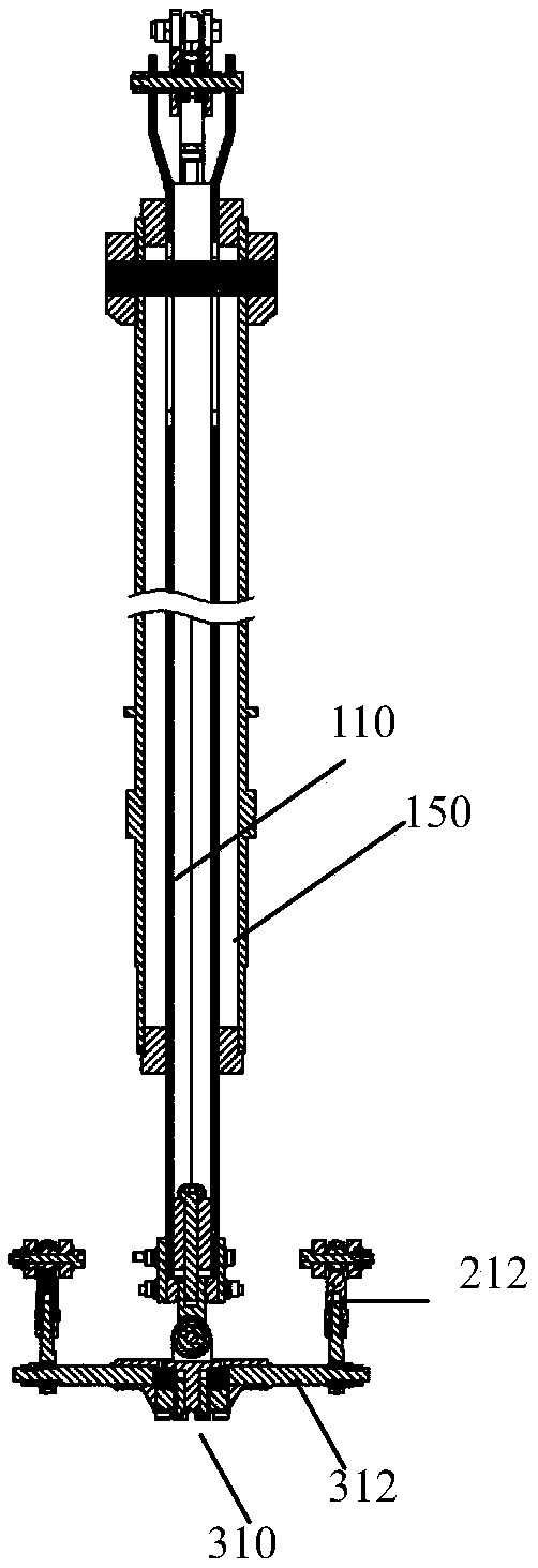
[0052] A helicopter rotor device of the present invention includes the rotor control device and the tubular rotor shaft 150, the total moment slide bar and the long tie rod are located in the rotor shaft, and the upper end of the rotor shaft is provided with a transverse Through the positioning pin shaft, the collective distance sliding rod is formed with an axial long hole matching the positioning pin shaft.

[0053] The limit pin of the collective slide bar is installed in the center of the rotor shaft, and only slides within a certain range in the up and down direction. Its sliding range is 10mm larger than the stroke range required by the rotor system. The collective distance slider limit pin plays a protective role on the collective distance slider. Prevent misuse from causing damage to the entire control mechanism.

[0054] Wherein, the upper and lower ends of the rotor shaft 150 are respectively connected with bolts to fix the limit block of the linkage rod, and the sa...


PUM


Abstract

The invention discloses a helicopter rotor wing operating device. The helicopter rotor wing operating device comprises a steering engine drive subassembly, a swash plate subassembly and a total torqueslide bar subassembly, wherein the steering engine drive subassembly comprises three linear steering engines having tail ends rotatably connected with an engine body, and three L-shaped operating arms which are correspondingly disposed with the linear steering engines and whose one ends are hinged with output ends of the linear steering engines and middle parts are rotatably connected with the engine body; the swash plate subassembly includes a swash plate and a swash plate rotating shaft sleeved in the swash plate; swash plate support arms are respectively installed in the traverse rolling direction and the pitching direction of the swash plate and are hinged with the other ends of the L-shaped operating arms; the total torque slide bar subassembly includes a central joint bearing disposed at the lower end of a total torque slide bar and a side joint bearing correspondingly disposed at the lower end of a long pull rod; a ball joint of the center joint bearing and the side joint bearing is fixedly connected with the swash plate rotating shaft through a traverse connecting rod. The self-stability and safety of an unmanned helicopter can be improved.

Description

technical field [0001] The invention belongs to the technical field of unmanned aerial vehicles, and in particular relates to a helicopter rotor control device and a rotor device. Background technique [0002] UAV flight control system, including multi-rotor UAV flight control system and fixed-wing unmanned helicopter flight control system. It is mainly used in the field of plant protection, power line inspection, geographical survey, logistics and transportation and other fields. A complete set of controls for unmanned helicopter flight. Including total moment, longitudinal, lateral and heading four control systems. The total moment control system can change the size of the rotor pull to control the helicopter's ascent and descent. The longitudinal and lateral control system can change the direction of the rotor pulling force in space to control the longitudinal and lateral displacement, pitch and roll motion of the helicopter. The heading control system can change the ...

Claims


Application Information

Patent Timeline
IPC IPC(8): B64C27/605
CPCB64C27/605
Inventor 刘帅孙涛贾良现
Owner 一飞智控(天津)科技有限公司
Why Eureka
Try Eureka