Soft sealing groove gate valve

A soft seal and groove technology, applied to the valve details, valve device, valve housing structure, etc., can solve the problems of high cost of installation, disassembly and maintenance, high error rate of operation, and complicated operation process, so as to save manpower, manufacture Simple, easy-to-install effect

Inactive Publication Date: 2019-04-26
TIANJIN HONGYI VALVE CO LTD
View PDF0 Cites 0 Cited by
  • Summary
  • Abstract
  • Description
  • Claims
  • Application Information

AI Technical Summary

Problems solved by technology

[0004] The problems of the above-mentioned installation method are: 1. The installation, disassembly and maintenance costs are high, time-consuming and labor-intensive
2. There are many installation procedures, the operation process is relatively complicated, and the operation error rate is high

Method used


Image

  • Soft sealing groove gate valve
  • Soft sealing groove gate valve
  • Soft sealing groove gate valve

Examples


Embodiment Construction

[0020] The present invention will be further described in detail below in conjunction with the accompanying drawings and through specific embodiments.

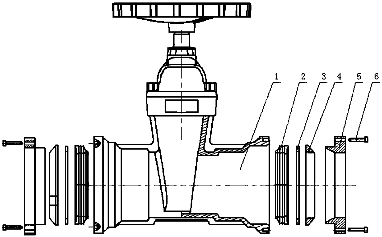
[0021] A soft-sealing grooved gate valve includes a valve body 1 and a pressure flange 5, the left and right ends of the valve body are coaxially installed with pressure flanges, and the pressure flange is connected with the valve body through screws 6.

[0022] The innovation point of the present invention is:

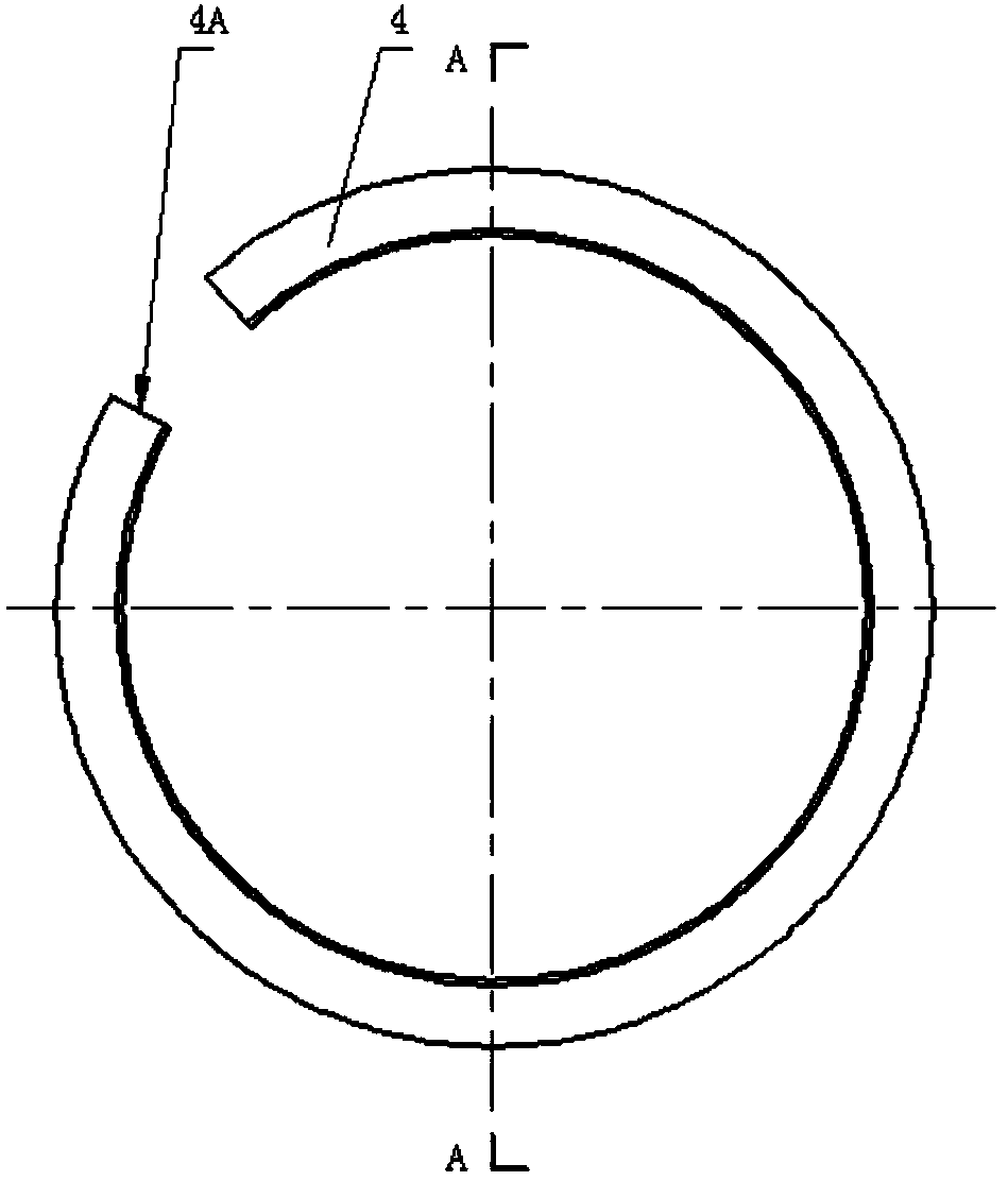
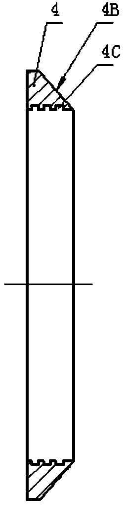
[0023] 1. A sealing ring 2, a pressure ring 3 and a C-shaped hoop ring 4 are installed in the valve body on the inner side of the pressure flange in sequence from the inside to the outside. The structure of the C-shaped hoop ring is as figure 2 , image 3 As shown, an opening 4A is formed on one side of the C-shaped hoop ring, and the surface of the C-shaped hoop ring in contact with the pressure flange is a tapered surface 4B. The C-shaped clamping ring and the pressure flange are connected by a tapered surface, ...


PUM


Abstract

The invention relates to a soft sealing groove gate valve. The soft sealing groove gate valve comprises a valve body and pressure flanges. The left end portion and right end portion of the valve bodyare coaxially provided with the pressure flanges. The pressure flanges are connected with the valve body through screws. Sealing rings, pressure rings and C-type clamping rings are sequentially and compactly arranged from inside to outside in the portion, on the inner sides of the pressure flanges, of the valve body. One sides of the C-type clamping rings are provided with openings. The surfaces,making contact with the pressure flanges, of the C-type clamping rings are conical surfaces. According to the gate valve, the pressure flanges are in conical surface connection with the C-type clamping rings; the connection mode is simple in structure and facilitates installation; and most importantly, the axial pressure of the pressure flanges is converted into the radial clamping force of the C-type clamping rings, the converted radial force increases as the axial force increases, and a pipeline is firmly clamped by the C-type clamping rings. The inner and outer edges of the sealing rings ofthe gate valve are provided with a plurality of annular convex edges. The flow direction of media in the annular convex edges is opposite to the flow direction of media in the pipeline. The performance of sealing the pipeline and the valve body is better as more media flow in.

Description

technical field [0001] The invention belongs to the field of valves, and relates to a gate valve, in particular to a soft-seal groove gate valve. Background technique [0002] Valves are widely used in water supply and drainage of fluid pipelines, fire control, air conditioning, gas, petroleum, chemical, water treatment, municipal, shipbuilding and other pipeline projects as control fluids, with cut-off, adjustment, diversion, reverse flow prevention, voltage stabilization, diversion Or overflow pressure relief and other functions. [0003] During the installation process of gate valves, traditional gate valve connection methods include: flanges, internal and external threads, socket welding, clamps, etc. [0004] The problems of the above-mentioned installation method are: 1. The cost of installation, disassembly and maintenance is high, time-consuming and labor-intensive. 2. There are many installation procedures, the operation process is relatively complicated, and the ...

Claims


Application Information

Patent Timeline
IPC IPC(8): F16K27/04F16L23/024F16L23/18
CPCF16K27/047F16L23/024F16L23/18
Inventor 曹继成
Owner TIANJIN HONGYI VALVE CO LTD
Why Eureka
Try Eureka