
Detecting device and method for cleanliness of oil liquid and hydraulic machine

A detection device and cleanliness technology, which is applied in the direction of measuring devices, optical testing of flaws/defects, and material analysis through optical means, can solve the problems of expensive instruments and high cost of detection devices, so as to improve accuracy and avoid oil pollution , to ensure the effect of cleanliness

Inactive Publication Date: 2019-04-26
SANY AUTOMOBILE MFG CO LTD
View PDF6 Cites 6 Cited by
  • Summary
  • Abstract
  • Description
  • Claims
  • Application Information

AI Technical Summary

Problems solved by technology

Although this method is time-consuming, the instrument is expensive, resulting in high cost of the detection device

Method used


Image

  • Detecting device and method for cleanliness of oil liquid and hydraulic machine
  • Detecting device and method for cleanliness of oil liquid and hydraulic machine

Examples


Embodiment 1

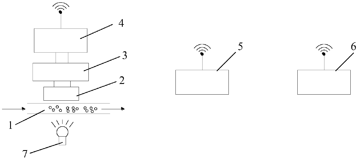
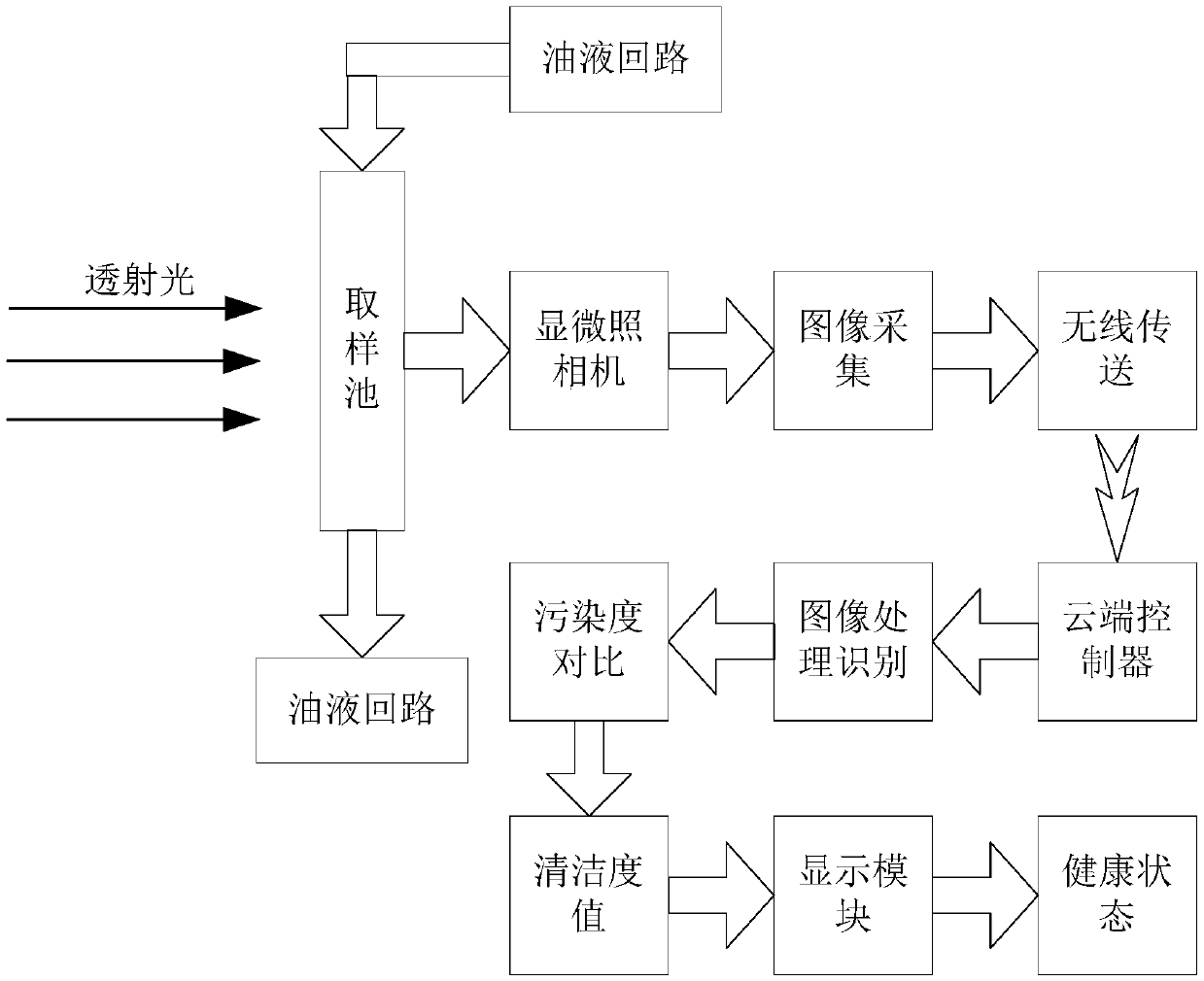
[0048] Such as figure 1 and figure 2 As shown, the oil cleanliness detection device includes: a sampling pool 1, a microscopic image acquisition module and a processing module, the inlet and outlet of the sampling pool 1 are respectively connected to the oil circuit of the hydraulic machine, and the microscopic image acquisition module includes a microscopic camera 2 , the image acquisition card 3 and the local controller 4, the microscopic camera 2 is used to take pictures and samples the oil in the sampling pool 1, to obtain microscopic images, the image acquisition card 3 is connected with the microscopic camera 2 and the local controller 4, The processing module includes a cloud controller 5 and a cloud storage. The local controller 4 and the cloud controller 5 are respectively connected with a wireless transmission module to realize signal transmission between the local controller 4 and the cloud controller 5. The cloud storage is used to store oil For the pattern datab...

Embodiment 2

[0059] The oil cleanliness detection device includes: a sampling pool, a microscopic image acquisition module and a processing module. The inlet and outlet of the sampling pool are respectively connected to the oil circuit of the hydraulic machine. The micro camera is used to take pictures of the oil in the sampling pool to obtain microscopic images. The processing module includes a local controller and a local memory. The image acquisition card is connected with the microscopic camera and the local controller. The local memory is used to store the oil. In the pattern database under different pollution degrees, the local controller is used to compare and analyze the microscopic image with the patterns in the pattern database to obtain the cleanliness of the oil.

[0060] In this scheme, the pattern database is stored in the local memory, and the local controller compares the microscopic image with the pattern in the local memory to obtain the cleanliness of the oil. This scheme...


PUM


Abstract

The invention provides a detecting device and method for cleanliness of oil liquid and a hydraulic machine. The detecting device comprises a sampling pool, a microscopic image collecting module and aprocessing module, wherein the sampling pool is provided with an inlet which oil liquid flows into and an outlet which the oil liquid flows out of; the microscopic image collecting module is used forcollecting microscopic images of the oil liquid which flows through the sampling pool; the processing module compares the microscopic images with images of oil liquid under different pollution degreesin a database, so that the cleanliness of the oil liquid is obtained. The detection mode is short in consumed time, the cleanliness of the oil liquid is obtained through program analysis, there are no subjective influences of staff, and in this way, the errors are small; the microscopic image collecting module is low in price, and therefore the cost for the detecting device is low; the inlet andthe outlet of the sampling pool are connected with an oil liquid loop separately, the sampling pool does not affect oil liquid circulation of the hydraulic machine, in this way, the cleanliness of theoil liquid can be detected when the hydraulic machine operates normally, and then the cleanliness of the oil liquid is monitored in real time.

Description

technical field [0001] The present invention relates to the technical field of oil cleanliness detection, and more specifically, to an oil cleanliness detection device, a hydraulic machine equipped with the oil cleanliness detection device, and an oil cleanliness detection method. Background technique [0002] In the lubrication system and hydraulic system of hydraulic machinery, wear is inevitable. In order to ensure the normal operation of the lubrication system and hydraulic system, it is necessary to know the condition of the oil in time, capture the potential accidents that have not yet occurred, and ensure the safe operation of the equipment , Avoid paying expensive repair costs, reduce loss of downtime for repairs, and reduce maintenance costs. The current detection methods of oil cleanliness mainly include ferrography analysis and particle counter. Ferrography analysis is realized in the laboratory by ferrography, that is, regular sampling in the oil circuit, pretre...

Claims


Application Information

Patent Timeline
Patent Type & Authority Applications(China)
IPC IPC(8): G01N21/94G01N21/03
CPCG01N21/03G01N21/94
Inventor 贺电卢志学曾斌
Owner SANY AUTOMOBILE MFG CO LTD
Learn More