Multi-channel parallel light path compression assembly and receiving optical member thereof

A parallel light, multi-channel technology, used in optical components, light guides, optics, etc., can solve problems such as difficulty in mass production, and achieve the effects of small size, easy interchangeability, and high reliability

Inactive Publication Date: 2019-04-26
LINKTEL TECH CO LTD
View PDF6 Cites 7 Cited by
  • Summary
  • Abstract
  • Description
  • Claims
  • Application Information

AI Technical Summary

Problems solved by technology

For the demux filter assembly with parallel optical paths with a pitch interval of 750um, the existing processing technology can still be mass-produced, but for smal

Method used


Image

  • Multi-channel parallel light path compression assembly and receiving optical member thereof
  • Multi-channel parallel light path compression assembly and receiving optical member thereof
  • Multi-channel parallel light path compression assembly and receiving optical member thereof

Examples


Embodiment 1

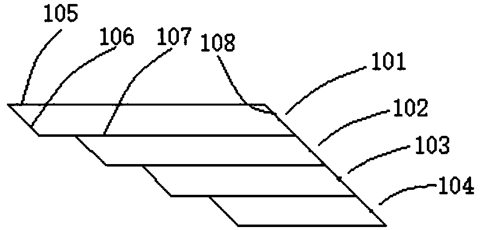
[0039] Such as figure 1 As shown, the optical path compression assembly provided in this embodiment includes four prisms, namely prism one 101, prism two 102, prism three 103 and prism four 104, and their lengths are L1, L2, L3, L4 respectively. The four prisms All are surrounded by its first working surface 105, second working surface 107, first reflecting surface 106 and second reflecting surface 108 to form a parallelogram, the first working surface 105 is parallel to the second working surface 107, the first working surface 105 is parallel to the second working surface 107, A working surface 105 is perpendicular to the input light, and the incident angle of the input light on the first reflective surface 106 is 45°. Among them, the pitch interval of the input four-channel light wave is P1, the pitch interval of the output four-channel light wave is P2, and the length difference ΔP=P1-P2 of the four prisms, that is, the length of the first prism 101 is L1, and the length of...

Embodiment 2

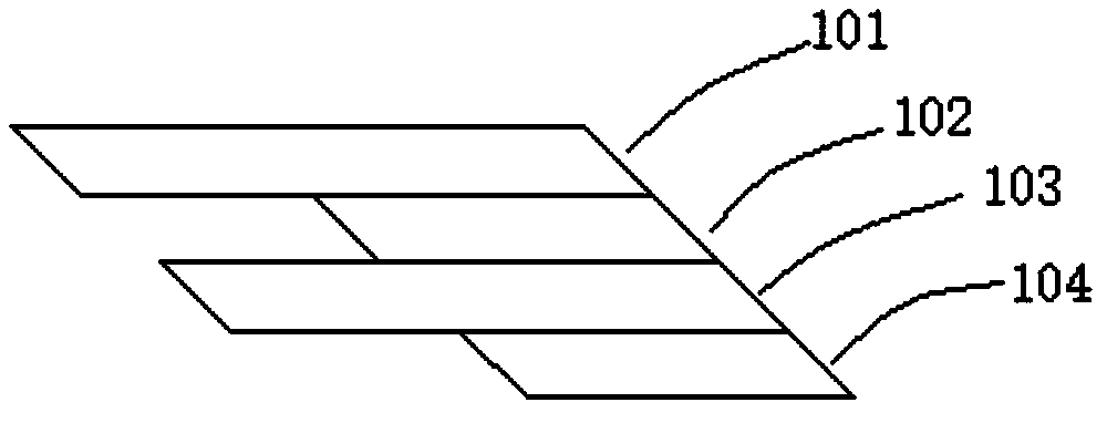
[0044] Such as image 3 As shown, the optical path compression assembly provided in this embodiment includes four prisms, namely prism one 101, prism two 102, prism three 103 and prism four 104, and their lengths are L1, L2, L3, L4 respectively. The four prisms All are surrounded by its first working surface 105, second working surface 107, first reflecting surface 106 and second reflecting surface 108 to form a parallelogram, the first working surface 105 is parallel to the second working surface 107, the first working surface 105 is parallel to the second working surface 107, A working surface 105 is perpendicular to the input light, and the incident angle of the input light on the first reflective surface 106 is 45°. Wherein, the pitch interval of the input four-channel light wave is P1, and the pitch interval of the output four-channel light wave is P2, then the length of prism one 101 is L1, the length of prism two 102 is L2=L1-(2*P1-P2), and the length of prism three 103...

Embodiment 3

[0048] Such as Figure 5 As shown, the optical path compression component of this embodiment is a variation structure of the optical path compression component of Embodiment 2, the difference lies in the order of the wavelengths of the input beams. Specifically, the optical path compression assembly includes four prisms, namely prism one 101, prism two 102, prism three 103 and prism four 104, the lengths of which are L1, L2, L3, and L4 respectively, and the four prisms are composed of The first working surface 105, the second working surface 107, the first reflecting surface 106 and the second reflecting surface 108 enclose a parallelogram, the first working surface 105 is parallel to the second working surface 107, and the first working surface 105 It is perpendicular to the input light, and the incident angle of the input light on the first reflective surface 106 is 45°. Wherein, the pitch interval of the input four-channel light wave is P1, and the pitch interval of the ou...


PUM


Abstract

The invention provides a multi-channel parallel light path compression assembly. The compression assembly comprises multiple prisms which sequentially overlap, the prisms are provided with first working surfaces used for light input, second working surfaces used for light output, first reflection surfaces which are used for receiving and reflecting input lights of the first working surfaces and second reflection surfaces which are used for receiving and reflecting output lights of the second working surfaces, the first and second working surfaces of the two adjacent prisms fit and overlap, andthe distance between the first reflection surfaces of the two adjacent prisms is greater than the distance between the second reflection surfaces of the two adjacent prisms. The compression assemblyhas the advantages that a light path is effectively compressed in the horizontal direction through a manner in which the prisms of corresponding multi-channel light waves are mutually staggeredly or equidistantly arranged, and therefore the compatibility of a large pitch interval of an optical filter assembly and a small pitch interval of a detector chip is achieved.

Description

technical field [0001] The invention belongs to the technical field of optical devices and modules for optical communication, and specifically relates to a multi-channel parallel optical path compression component and its receiving optical device, which can be applied to CWDM and LWDM wavelengths and can be packaged in modules such as QSFP+, QSFP28, QSFP DD, and OSFP middle. Background technique [0002] For high-speed light-receiving devices in BOX packaging, the compatibility of optical structure and electrical structure must be considered in product design, especially TIA chips, the key core material of electricity. TIA is limited by manufacturers and other sources of supply, and is limited by the industrial level of the industry. The pitch interval (that is, the center interval) of the multi-channel input electrodes of many TIAs is usually small in size such as 750um, 500um, and 250um. In order to reduce the attenuation and parasitic parameters of the electrical signal,...

Claims


Application Information

Patent Timeline
IPC IPC(8): G02B6/42
CPCG02B6/4204
Inventor 胡百泉李林科林雪枫胡定坤吴天书杨现文张健
Owner LINKTEL TECH CO LTD
Why Eureka
Try Eureka