
Evaluation method, device and system for fatigue life of weld joint of wagon body

A fatigue life, railway freight car technology, applied in instrumentation, geometric CAD, calculation, etc., can solve the problem of low accuracy of weld fatigue prediction

Active Publication Date: 2019-04-26
CRRC QIQIHAR ROLLING CO LTD
View PDF8 Cites 4 Cited by
  • Summary
  • Abstract
  • Description
  • Claims
  • Application Information

AI Technical Summary

Problems solved by technology

[0005] Embodiments of the present invention provide a method, device, and system for evaluating the fatigue life of railway freight car body welds, so as to at least solve the technical problem of relatively low prediction accuracy of freight car body weld fatigue in the prior art

Method used


Image

  • Evaluation method, device and system for fatigue life of weld joint of wagon body
  • Evaluation method, device and system for fatigue life of weld joint of wagon body
  • Evaluation method, device and system for fatigue life of weld joint of wagon body

Examples


Embodiment 1

[0043] According to an embodiment of the present invention, a method embodiment of a method for evaluating the fatigue life of a railway freight car body weld seam is provided. It should be noted that the steps shown in the flow chart of the accompanying drawings can be executed in a set of computer-executable instructions such as and, although a logical order is shown in the flowcharts, in some cases the steps shown or described may be performed in an order different from that shown or described herein.

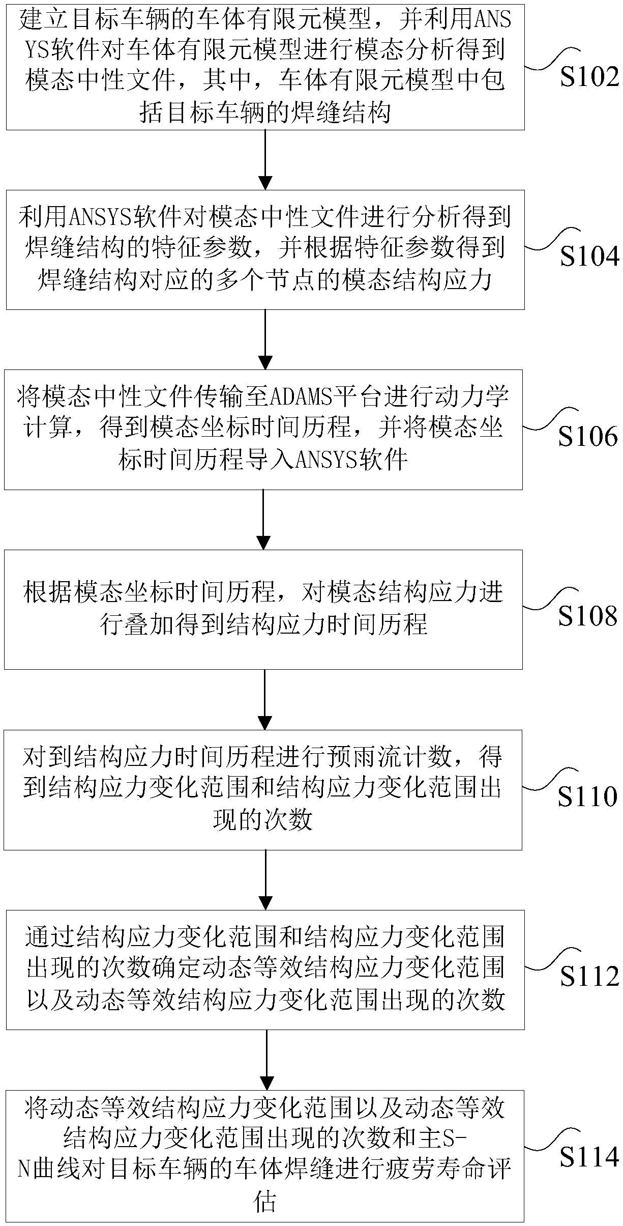
[0044] figure 1 It is a flow chart of the method for evaluating the fatigue life of the weld seam of the railway wagon car body according to an embodiment of the present invention, such as figure 1 As shown, the evaluation method for the fatigue life of the welded seam of the railway freight car body includes the following steps:

[0045] Step S102, establishing a finite element model of the vehicle body of the target vehicle, and performing modal analysis on the finite ele...

Embodiment 2

[0081] According to the embodiment of the present invention, a device for evaluating the fatigue life of the weld seam of the railway freight car body is also provided. The evaluation method for the fatigue life of the weld seam of the railway freight car body provided by the example. The apparatus for evaluating the fatigue life of the weld seam of the railway freight car body provided by the embodiment of the present invention is introduced below.

[0082] Figure 6 It is a schematic diagram of an evaluation device for the fatigue life of a railway wagon body weld seam according to an embodiment of the present invention, as Figure 6 As shown, the evaluation device for the fatigue life of the weld seam of the railway freight car body includes: a first analysis unit 601, a second analysis unit 603, a first acquisition unit 605, a second acquisition unit 607, a third acquisition unit 609, and a determination unit 611 and an evaluation unit 613 . The following is a detailed ...


PUM


Abstract

The invention discloses a method, a device and a system for evaluating fatigue life of a welding seam of a wagon body. The method comprises the following steps: obtaining characteristic parameters ofa weld joint structure based on ANSYS software, and obtaining modal structure stress of a plurality of nodes of the weld joint structure according to the characteristic parameters; Transmitting the modal neutral file to an ADAMS platform to obtain a modal coordinate time history; Superposing the modal structural stress to obtain a structural stress time history; Carrying out pre-rain flow countingon the structural stress time history to obtain a structural stress change range and the occurrence frequency of the structural stress change range; Determining a dynamic equivalent structure stresschange range and the occurrence frequency of the dynamic equivalent structure stress change range; Dynamic equivalent structure stress change range, occurrence frequency of dynamic equivalent structure stress change range and main S-N curve are used to evaluate the fatigue life of the vehicle body weld joint. The technical problem that in the prior art, the prediction precision of truck body weldjoint fatigue is low is solved.

Description

technical field [0001] The invention relates to the technical field of fatigue life evaluation, in particular to a method, device and system for evaluating the fatigue life of weld seams of railway wagon car bodies. Background technique [0002] The fatigue reliability of railway wagons is very important, and it is one of the key factors affecting the safety of operation. The weak part of the fatigue reliability of the car body is the welded joint. In the operating environment, weld cracking of the welded structure is one of the main forms of structural failure, and the fatigue life of the welded structure determines the service life of the car body. At present, the fatigue life of the vehicle body is generally evaluated by means of real vehicle tests and computer-aided techniques. The actual vehicle test results are relatively accurate, but the cycle is longer and the cost is higher, resulting in low fatigue life prediction accuracy and limited engineering application valu...

Claims


Application Information

Patent Timeline
IPC IPC(8): G06F17/50
CPCG06F30/15G06F30/23G06F2119/06Y02T90/00
Inventor 赵尚超李向伟赵春雷李文全付勇张强
Owner CRRC QIQIHAR ROLLING CO LTD
Learn More