Distributed-type inertial brushless excitation synchronous power generator

A synchronous generator and inertia type technology, which is applied to synchronous generators, electrical components, electromechanical devices, etc., can solve the problem of large local inertia of the mass flywheel shafting, reduced mechanical stability and reliability of the generator shafting, and inability to guarantee The generator continues to stabilize the output and other problems, and achieves the effect of solving reliability problems and compensating for sudden changes in voltage.

Active Publication Date: 2019-04-26
WOLONG ELECTRIC GRP CO LTD +1
View PDF9 Cites 4 Cited by
  • Summary
  • Abstract
  • Description
  • Claims
  • Application Information

AI Technical Summary

Problems solved by technology

[0003] Although the commonly used brushless excitation synchronous generator can guarantee the start-up, grid connection and operation functions in the normal grid environment through the automatic voltage regulator (AVR), but when the power grid has instantaneous power failure, switching, flicker and other working conditions, it will automatically The voltage regulator AVR cannot guarantee the continuous and stable output of the generator
In addition, the existing design adopts a single inertia flywheel at the shaft extension end, and the single flywheel must be relatively large. The local inertia of the flywheel shaft system is too large, which reduces the mechanical stability and reliability of the entire generator shaft system.

Method used


Image

  • Distributed-type inertial brushless excitation synchronous power generator
  • Distributed-type inertial brushless excitation synchronous power generator
  • Distributed-type inertial brushless excitation synchronous power generator

Examples


Embodiment Construction

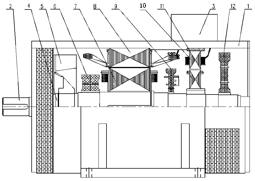
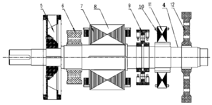
[0026] Such as figure 1 and figure 2 As shown, the present invention includes a machine base 1, a rotating shaft 2, a junction box 3 and an inertia distribution type rotor assembly. The inertia distribution type rotor assembly is sleeved on the rotating shaft 2. The components are integrated in the machine base 1, and the junction box 3 is arranged outside the machine base 1; the inertia distribution type rotor assembly includes a fan 5, a first auxiliary flywheel 6, a synchronous generator excitation 7, a rotating rectifier disc 9, an excitation generator motor Pivot 11 and second auxiliary flywheel 12. The inertial rotor section 4, fan 5, first auxiliary flywheel 6, synchronous generator excitation 7, rotating rectifier disc 9, excitation generator armature 11 and second auxiliary flywheel 12 are arranged in sequence from left to right.

[0027] The said rotating shaft 2 is divided into left section, middle section and right section successively from left to right. Inert...


PUM


Abstract

The invention discloses a distributed-type inertial brushless excitation synchronous power generator. The distributed-type inertial brushless excitation synchronous power generator comprises a generator base, a rotating shaft, a junction box and an inertial-distributed-type rotor assembly, the inertial-distributed-type rotor assembly sleeve the rotating shaft, the rotating shaft penetrates throughthe generator base in the left-right direction, the rotating shaft and the inertial-distributed-type rotor assembly are integrated in the generator base, and the junction box is arranged outside thegenerator base; and the inertial-distributed-type rotor assembly comprises a fan, a first auxiliary flywheel, a synchronous power generator excitator, a rotary rectifier disc, an excitation power generator armature and a second auxiliary flywheel. The large distributed-type inertia of the power generator is utilized for energy storage under the special environments such as interference electricityand flickering of a power source, mechanical energy is converted to electric energy, short-time voltage leap is compensated, reliable supplying with the continuous output voltage and stable frequencyof the power generator is achieved through automatic loading, and the reliability problem of an emergency power supply system is solved.

Description

technical field [0001] The invention relates to the technical field of generators, in particular to a distributed inertia type brushless excitation synchronous generator. Background technique [0002] The brushless excitation synchronous generator includes a main synchronous generator and an AC exciter. The AC exciter is a small synchronous generator mainly composed of the AC exciter poles and the AC exciter rotor. The rotor of the AC exciter is an armature, which outputs three-phase alternating current, which is rectified into direct current by the rotating rectifier disc to provide the main excitation current for the main synchronous generator. [0003] Although the commonly used brushless excitation synchronous generator can guarantee the start-up, grid connection and operation functions in the normal power grid environment through the automatic voltage regulator (AVR), when the power grid has instantaneous power failure, switching, flicker and other working conditions, i...

Claims


Application Information

Patent Timeline
Patent Type & Authority Applications(China)
IPC IPC(8): H02K7/02H02K19/16H02K19/38H02K9/06
CPCH02K7/025H02K9/06H02K19/16H02K19/38Y02E60/16
Inventor 张浩张虎张雅刘平顺闫忠
Owner WOLONG ELECTRIC GRP CO LTD
Why Eureka
Try Eureka