Underground pipeline identification and monitoring system and use method

A technology for underground pipelines and monitoring systems, applied in measuring devices, instruments, etc., can solve problems such as loss, lack of standardized management, pipeline accidents, etc., and achieve the effects of anti-electromagnetic interference and radiation, high spatial resolution, and broad application prospects

Inactive Publication Date: 2019-04-30
HOHAI UNIV
View PDF5 Cites 5 Cited by
  • Summary
  • Abstract
  • Description
  • Claims
  • Application Information

AI Technical Summary

Problems solved by technology

With the rapid development of urban construction, my country has increased the development and utilization of underground space in recent years, and more and more underground pipelines have been laid in cities. Due to the incompleteness of archives, the situation of the underground pipeline is unclear. In addition, the concealment of the underground pipeline makes it impossible to determine the actual location and burial depth of the pipeline. During the construction process, the damage to the underground pipeline occurs from time to time. Retrofit brings danger
If the pipeline is not monitored, repaired and cleaned up in time, accidents may occur and unnecessary losses will be caused
There has been a long history of research and application of pipeline identification and monitoring methods, but due to the complexity of pipeline identification and monitoring due to different materials, pipeline transport media, and environments, there is currently no general method that can fully meet the requirements Various pipeline identification and monitoring requirements

Method used


Image

  • Underground pipeline identification and monitoring system and use method
  • Underground pipeline identification and monitoring system and use method
  • Underground pipeline identification and monitoring system and use method

Examples


Embodiment Construction

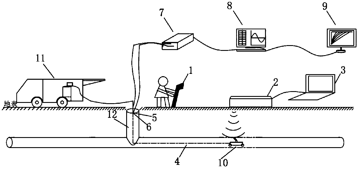
[0029] Such as figure 1 As shown, the identification and monitoring system of the present invention includes a pipeline instrument 1, a geological radar 2, a strain sensing optical fiber 5, a temperature compensation optical fiber 6, an optical fiber data acquisition and transmission system 7, an optical fiber data processing and analysis system 8, and a monitoring result display system 9 1. A robot crawler 10 with a camera lens, a manipulation cable frame and a main controller 11 in the pipeline CCTV detection system. Such as figure 1 As shown, the pipeline instrument 1 and the ground radar 2 are used together to work together, and the output end of the ground radar 2 is connected to the computer display system 3 .

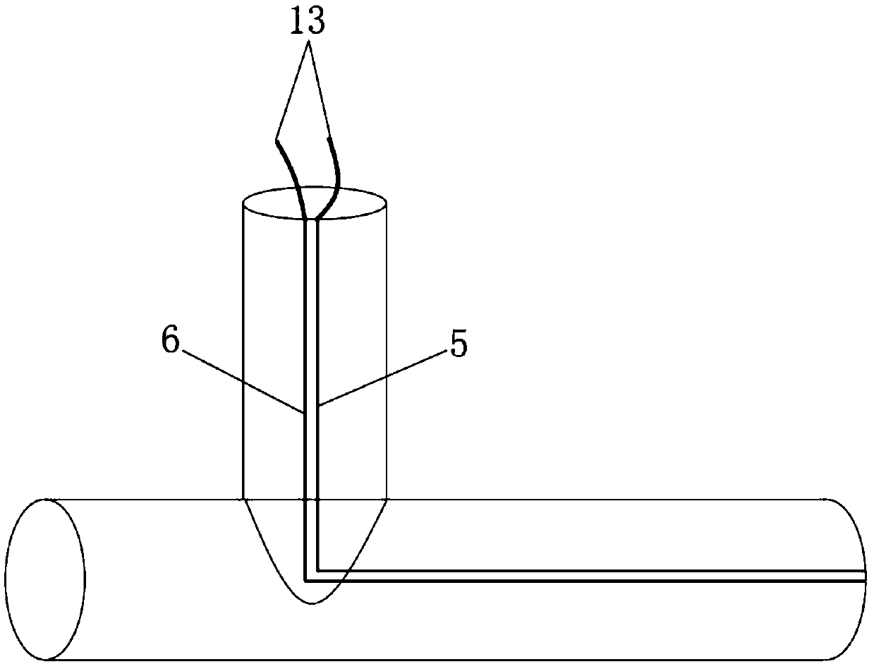
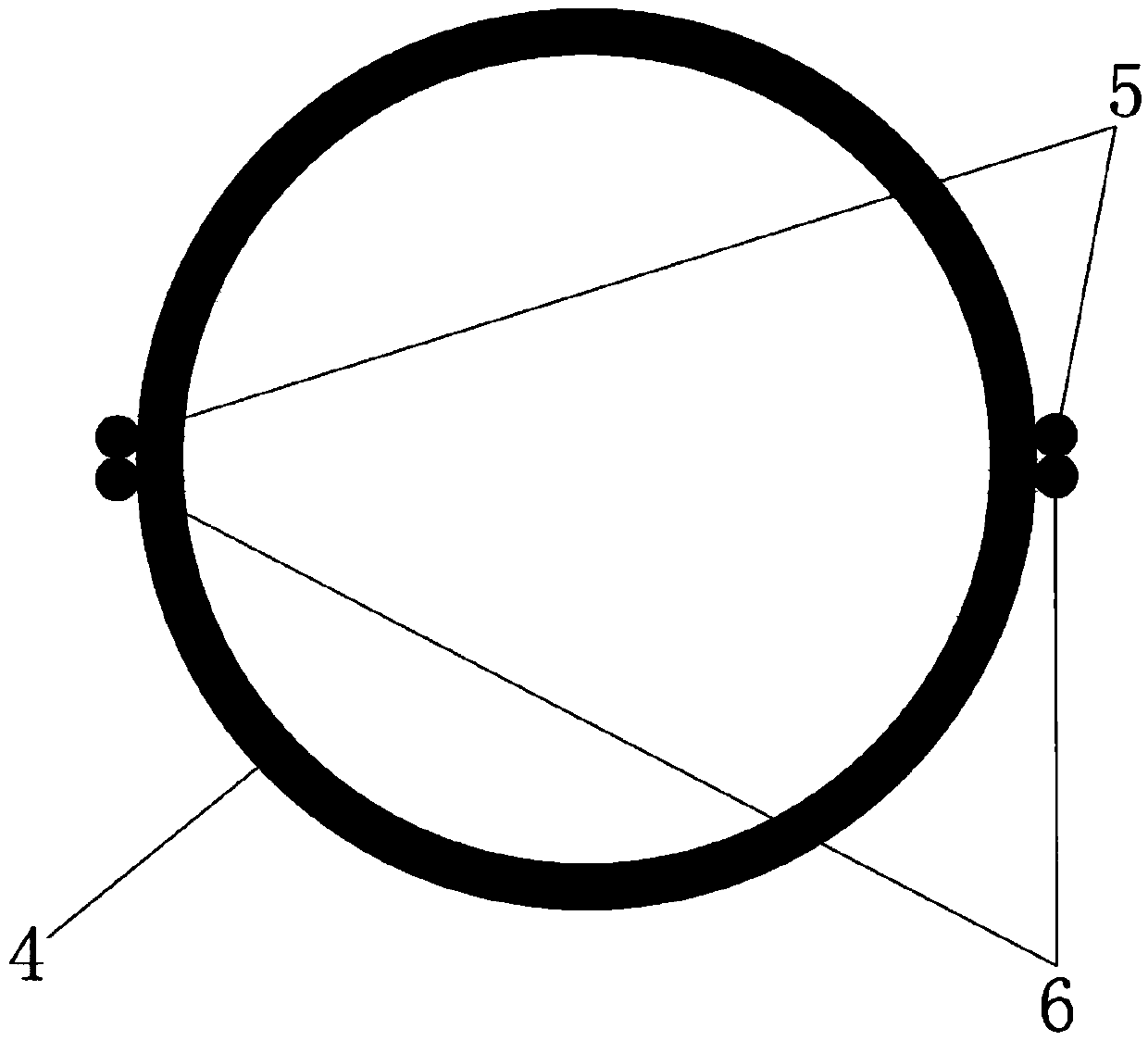
[0030] Such as figure 2 , image 3 As shown, the strain sensing optical fiber 5 and the temperature compensation optical fiber 6 are arranged symmetrically outside the pipeline, and one end of the arranged optical fiber is connected to the optical fiber data ...


PUM


Abstract

The invention discloses an underground pipeline identification and monitoring system and a use method. The system comprises a pipeline instrument and a geological radar, a strain sensing optical fiber, a temperature compensation optical fiber, an optical fiber data acquisition and transmission system, an optical fiber data processing and analysis system, a monitoring result display system and a pipeline CCTV (Closed Circuit Television Inspection) detection system. A pipeline is identified through the pipeline instrument and the geological radar; real-time optical fiber acquisition and transmission are carried out through distributed sensing optical fibers outside the pipeline and the optical fiber data acquisition and transmission system, and stress, temperature and deformation of the pipeline are obtained through the optical fiber data processing system; and the pipeline CCTV detection system is used for carrying out pipeline rust layer, scaling, corrosion, perforating, crack detection and camera shooting. The underground pipeline identification and monitoring system is rapid and accurate in positioning, long in monitoring distance, comprehensive in collected data and high in sensitivity and accuracy, and rapid and accurate identification and monitoring of the underground pipeline are achieved.

Description

technical field [0001] The invention relates to the technical field of underground pipeline network monitoring, in particular to an identification and monitoring system for underground pipelines and a use method. Background technique [0002] Urban underground pipelines are an important part of urban infrastructure. Underground pipelines are the "vessels" and "nerves" of cities, as well as the lifelines of cities. With the rapid development of urban construction, my country has increased the development and utilization of underground space in recent years, and more and more underground pipelines have been laid in cities. Due to the incompleteness of archives, the situation of the underground pipeline is unclear. In addition, the concealment of the underground pipeline makes it impossible to determine the actual location and burial depth of the pipeline. During the construction process, the damage to the underground pipeline occurs from time to time. Retrofits bring hidden dan...

Claims


Application Information

Patent Timeline
Patent Type & Authority Applications(China)
IPC IPC(8): G01D21/02
CPCG01D21/02
Inventor 高磊徐中权韩川滕健
Owner HOHAI UNIV
Why Eureka
Try Eureka