
Chip packaging method and chip packaging structure

A chip packaging structure and chip packaging technology, applied in the manufacture of electrical components, electrical solid devices, semiconductor/solid devices, etc., can solve problems such as chip stacking bottlenecks, and achieve the effects of easy operation, reduced adverse effects, and avoid warping

Active Publication Date: 2019-04-30
SEMICON MFG INT (SHANGHAI) CORP +1
View PDF3 Cites 2 Cited by
  • Summary
  • Abstract
  • Description
  • Claims
  • Application Information

AI Technical Summary

Problems solved by technology

CoW packaging technology has many advantages, such as the ability to achieve high integration of semiconductor devices, reduce the size of semiconductor packages, reduce the cost of final products, simplify the assembly process and improve yield, etc., but the packaging technology is currently achieving high throughput ( High Throughput) has a bottleneck in DieStacking

Method used


Image

  • Chip packaging method and chip packaging structure
  • Chip packaging method and chip packaging structure
  • Chip packaging method and chip packaging structure

Examples


Embodiment Construction

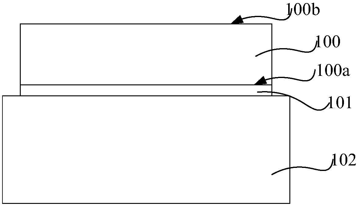
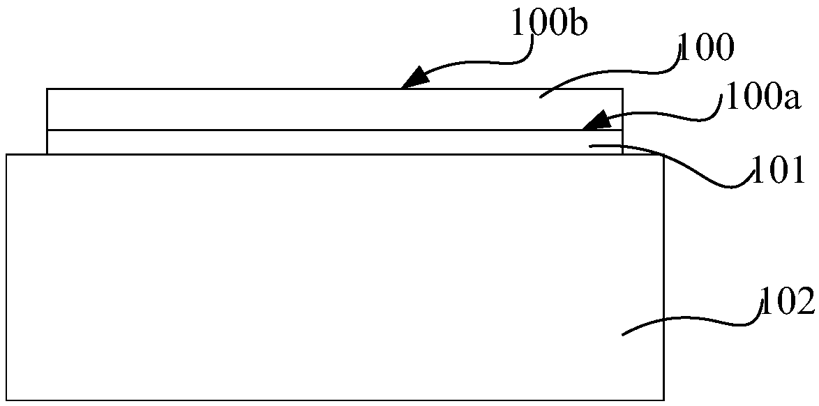
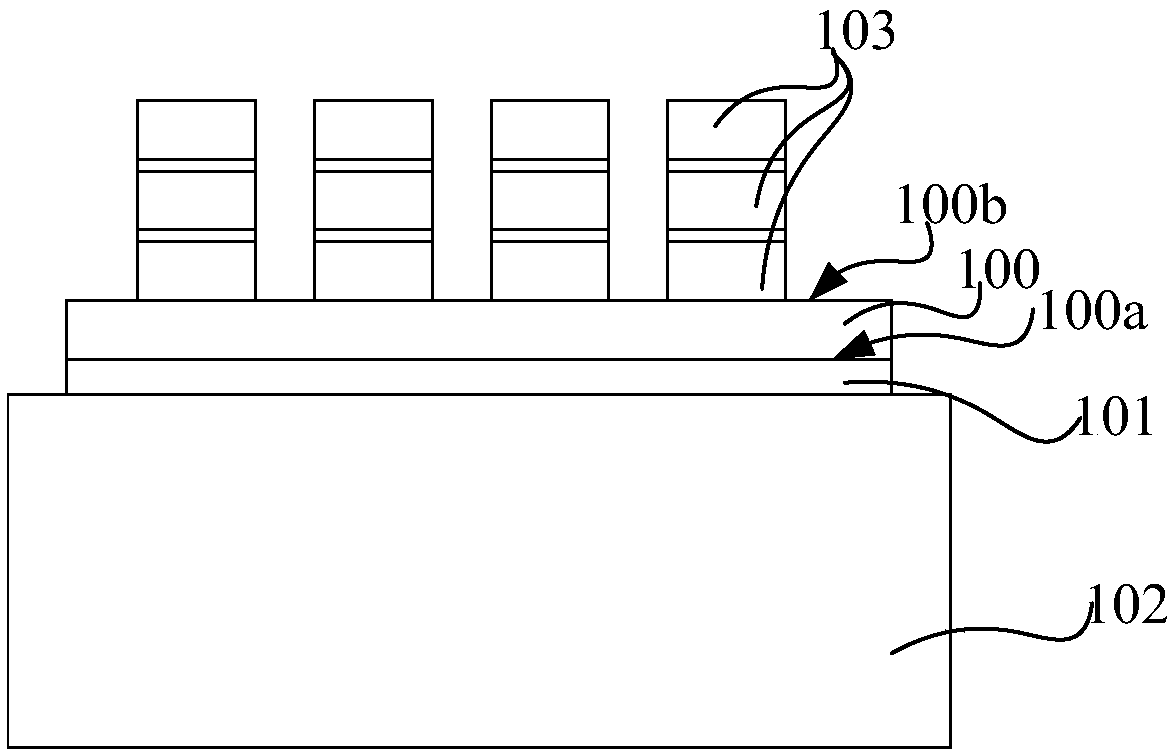
[0037] At present, the key processes in CoW packaging technology include Device Wafer Backside Grinding, Die Stacking and Die Saw. Auxiliary structures commonly used in thinning and wafer stacking processes are usually pasted on the front of the component wafer as a support for back thinning, or pasted on the front or back of the back-thinned component wafer for chip stacking support. Please refer to Figures 1A to 1C , a CoW encapsulation process includes:

[0038] First, please refer to Figure 1A , affixing the front side 100a of the element wafer 100 to a carrier 102 through a thermal tape (Thermal tape) 101, for supporting the element wafer 100 in subsequent processes;

[0039] Then, refer to Figure 1B , the back side 100b of the component wafer 100 is thinned by using a chemical mechanical polishing (CMP) process, so as to expose through silicon vias (Through Silicon Vias) in the component wafer 100 from the back side 100b of the component wafer 100 Via, TSV) and o...


PUM


Abstract

The invention provides a chip packaging method and a chip packaging structure. The chip packaging method includes pasting a first carrier with high heat conductivity on the front side of a component wafer with normal thickness so as to be used for supporting the component wafer in a component wafer backside thinning process, and rapidly transferring extra heat generated in the backside thinning process to reduce the unfavorable influences on the component wafer; and replacing the first carrier into a second carrier with low heat conductivity, or, pasting the second carrier with low heat conductivity on the back side of the component wafer and removing the first carrier so as to be used for supporting the component wafer in a process transferring the component wafer after backside thinning.Thus, operation on the component wafer can be realized, and the component wafer can be prevented from warping; and in a subsequent wafer stacking process, good heat preservation and maintenance of heat can be achieved by utilizing the characteristic that the heat conductivity of the second carrier is lower relative to the first carrier, so that the problem of high throughput bottleneck caused bythe high heat conductivity of the first carrier can be solved.

Description

technical field [0001] The invention relates to the technical field of integrated circuit manufacturing, in particular to a chip packaging method and a chip packaging structure. Background technique [0002] Chip on wafer (CoW) packaging technology, as one of the advanced packaging (Package) technologies, can stack multiple chips separately on the positions of good chips that are pre-identified on a device wafer (Device Wafer) (Die, that is, a block with complete functions cut out from the wafer) to realize the manufacture of three-dimensional semiconductor integrated circuit chips (Integrated Circuit, IC). CoW packaging technology has many advantages, such as the ability to realize the height of semiconductor device devices Integration, reducing the size of semiconductor packaging, reducing the cost of final products, simplifying the assembly process, and improving yield, etc., but this packaging technology currently has a bottleneck in realizing high throughput (High Throu...

Claims


Application Information

Patent Timeline
Patent Type & Authority Applications(China)
IPC IPC(8): H01L21/683H01L23/367
CPCH01L21/6835H01L23/3672H01L2221/68327
Inventor 陈彧
Owner SEMICON MFG INT (SHANGHAI) CORP
Learn More