Vacuum glue pouring method for permanent magnetism motor rotors

A permanent magnet motor and glue filling technology, which is applied in the manufacture of motor generators, stator/rotor bodies, electrical components, etc., can solve the problems of excessive glue loss, high labor intensity, difficulty in ensuring sufficient filling and glue filling quality, etc. , to achieve the effect of preventing tooth tension and glue loss, increasing the flow rate of glue injection, and shortening the time required for gelation

Active Publication Date: 2019-04-30
湖南中车商用车动力科技有限公司
View PDF8 Cites 13 Cited by
  • Summary
  • Abstract
  • Description
  • Claims
  • Application Information

AI Technical Summary

Problems solved by technology

[0004] The disadvantage of this solution is that the vinyl polymer anaerobic adhesive has a relatively high viscosity, about 13000-15000mPa·s at room temperature (25°C). Under high pressure, the glue flows slowly and pores are easy to form, especially for products with long cores, it is more difficult to operate, and it is impossible to ensure that the glue fully fills the gap; the natural drying time is longer, and there is glue leakage out of the iron core punching sheet 11 phenomenon, there is a lot of glue loss, it is difficult to ensure sufficient filling and glue filling quality, and the glue filling efficiency is low and the labor intensity is high
[0006] The disadvantage of this solution is that in addition to the above-mentioned problems such as excessive viscosity, it is difficult to ensure the uniformity of mixing by manually operating the glue filling tool for glue mixing

Method used


Image

  • Vacuum glue pouring method for permanent magnetism motor rotors
  • Vacuum glue pouring method for permanent magnetism motor rotors
  • Vacuum glue pouring method for permanent magnetism motor rotors

Examples


Embodiment 1

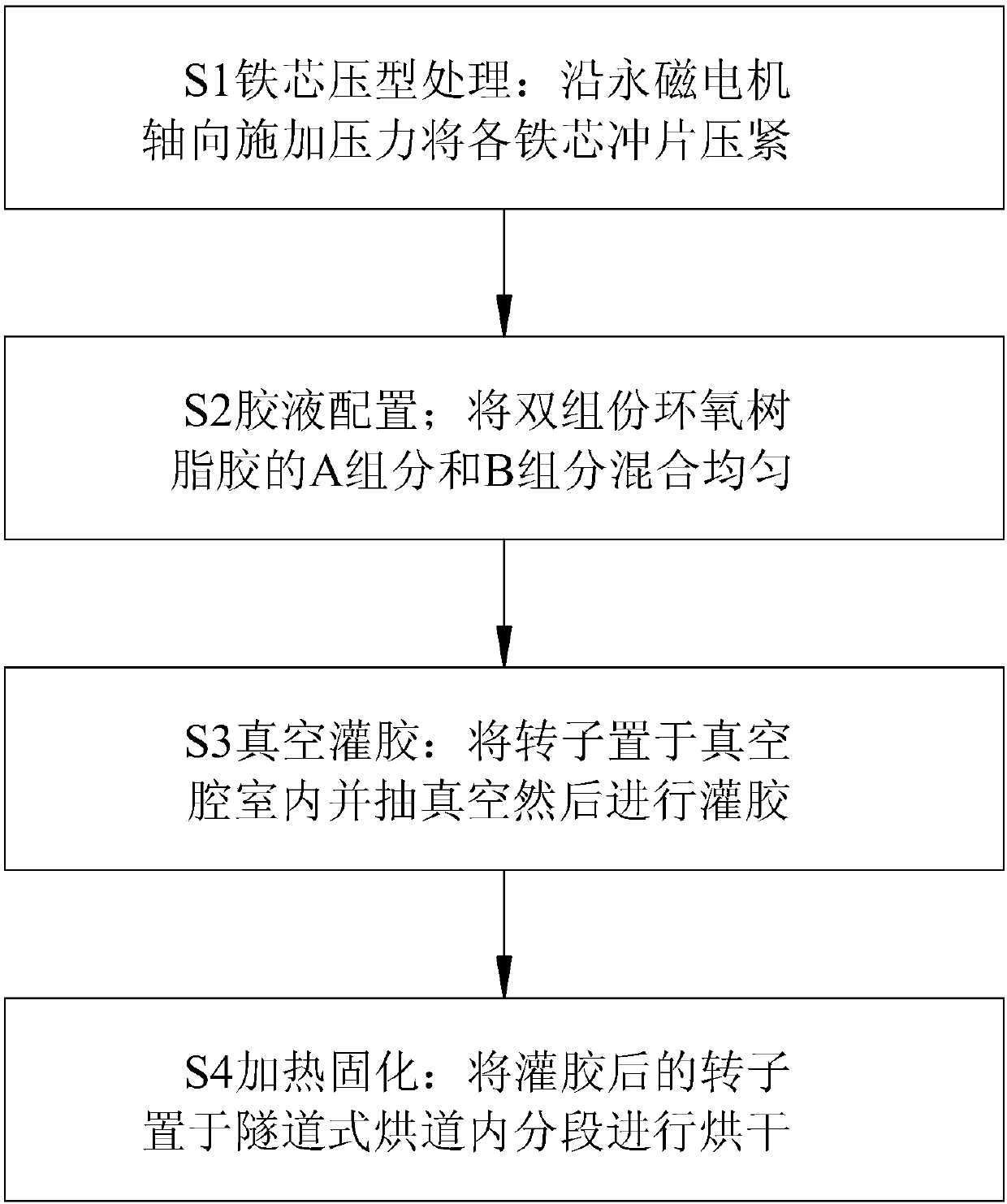
[0036] Figure 2 to Figure 5 , Figure 8 and Figure 9 An embodiment of the present invention is shown. The permanent magnet motor rotor vacuum filling method of this embodiment includes the following steps:

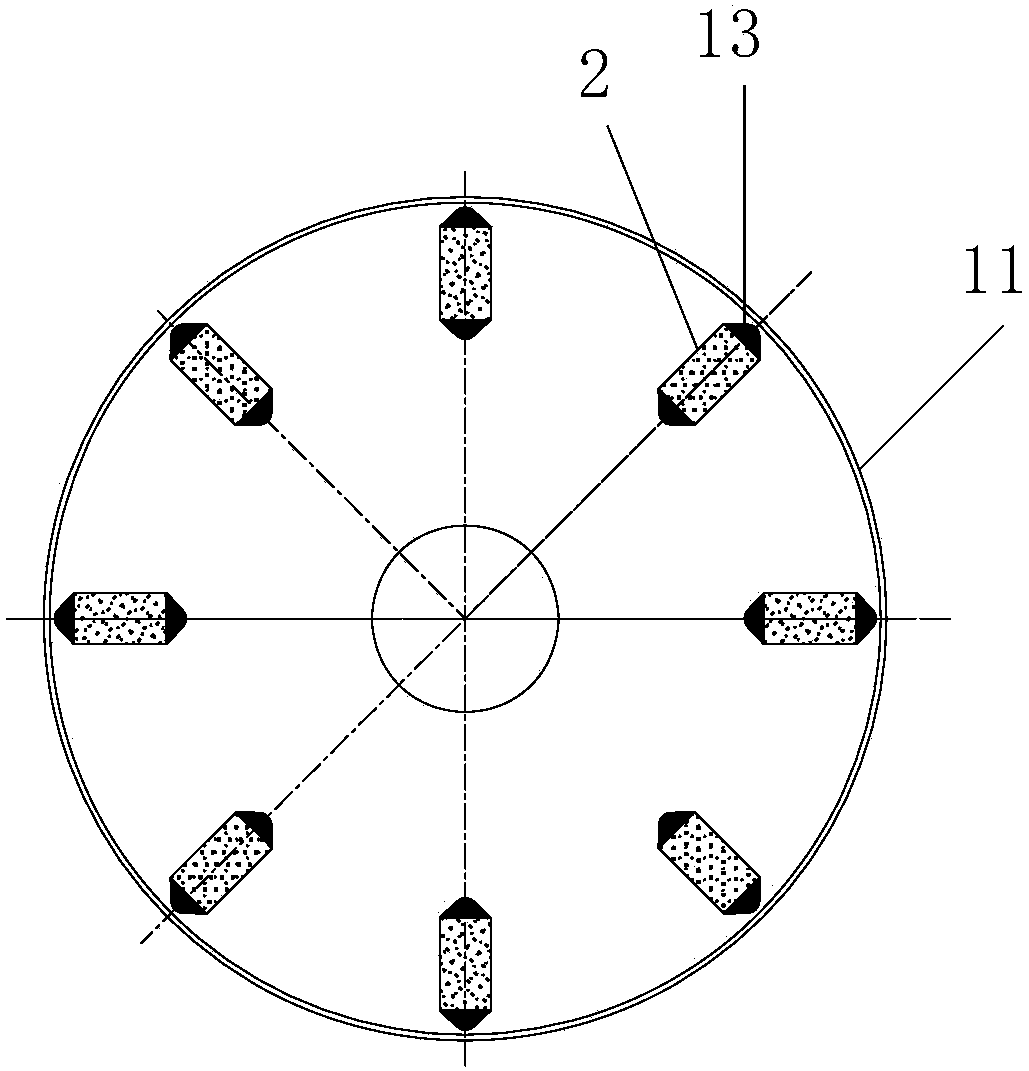
[0037] S1 rotor core 1 pressing process: apply pressure along the axial direction of the permanent magnet motor to compress each iron core punching piece 11;

[0038] S2 glue solution configuration; mix the A component and B component of the two-component epoxy resin glue evenly;

[0039] S3 Vacuum Glue Filling: Put the rotor in the vacuum chamber and evacuate and then glue the glue;

[0040] S4 Heating and curing: Place the filled rotor in a tunnel-type drying tunnel for drying in sections.

[0041]In the permanent magnet motor rotor vacuum glue filling method, the iron core 1 is molded before the glue is glued, and the iron core punches 11 are pressed tightly through the mold pressure to reduce the gap between the iron core punches 11, which is beneficial to preven...

Embodiment 2

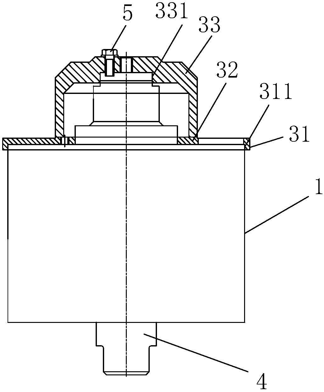
[0050] Image 6 and Figure 7 An embodiment of the present invention is shown. The glue filling scheme of this embodiment is basically the same as that of Embodiment 1, the difference is that in this embodiment, the iron core forming device includes an upper pressing plate 71, a lower pressing plate 72, and The tensioning assembly 73 used to tighten the upper pressing plate 71 and the lower pressing plate 72, the upper pressing plate 71 is provided with a stepped hole and is set on the stepped surface between the iron core 1 and the upper end of the rotor pressing ring 12, and the lower pressing plate 72 is provided with It has a stepped hole and is set on the stepped surface between the iron core 1 and the rotor pressure ring 12 at the lower end. Wherein, the tensioning assembly 73 can adopt tensioning screw rods and supporting lock nuts, and the tensioning assemblies 73 are arranged in four groups and distributed at the four corners. After locking the tensioning assembly 73...


PUM

PropertyMeasurementUnit
viscosityaaaaaaaaaa
diameteraaaaaaaaaa
lengthaaaaaaaaaa

Abstract

The invention discloses a vacuum glue pouring method for permanent magnetism motor rotors. The method includes the following steps: S1, a step of iron core profiling processing, namely the step of applying pressure to compress iron core punching sheets in an axial direction of a permanent magnetism motor; S2, a step of glue solution configuration, namely the step of uniformly mixing an A componentand B component of a two-component epoxy resin adhesive; S3, a step of vacuum glue pouring, namely the step of placing a rotor into a vacuum cavity to perform vacuum pumping, and then performing gluepouring; and S4, a step of heating and curing, namely the step of placing the rotor after glue pouring into a tunnel type baking channel to perform segment drying. The method has high glue pouring efficiency, tooth tension and glue loss phenomenon is not easy to occur, and the quality of products can meet the filling technical requirements of the permanent magnetism motor rotor.

Description

technical field [0001] The invention relates to a permanent magnet motor rotor assembly method, and specifically discloses a permanent magnet motor rotor vacuum filling method. Background technique [0002] The rotor of the permanent magnet motor is mainly composed of an iron core 1 , a magnetic steel 2 and a rotating shaft 4 . as attached figure 1 As shown, the magnetic steel 2 is embedded in the installation groove of the iron core punch 11, because a certain gap is left after the magnetic steel 2 is embedded, when the motor is running, the rotor will rotate at a high speed, and there are unfixed magnetic steel 2 in the rotor. There is a risk of displacement or fragmentation. At the same time, the movement of the magnetic steel 2 will destroy the dynamic balance of the rotor, thereby affecting the stability and reliability of the motor operation. Therefore, the gap filling after the magnetic steel 2 is embedded is very important. Only when the gap is fully filled can the ...

Claims


Application Information

Patent Timeline
Patent Type & Authority Applications(China)
IPC IPC(8): H02K15/03H02K15/12B05C5/00B05C11/10B05D3/02B05D7/24
CPCB05C5/00B05C11/1002B05C11/1042B05D3/0254B05D7/24B05D2504/00H02K15/03H02K15/12
Inventor 王新剑冯迎怀陈致初雷军罗祥程陈佳龙恒黄德聪杨轶殷茜元炯包华羽陈江秀
Owner 湖南中车商用车动力科技有限公司
Why Eureka
Try Eureka