Expandable small-sized chassis type battery swap station applying transfer trolley

A technology of changing power stations and trolleys, which is applied in the field of changing stations, which can solve the problems of not being able to fully automatically change batteries, low expansion, and large floor space, and achieve the effects of improving power changing effects, flexible transportation, and convenient transportation

Inactive Publication Date: 2019-05-03
XIAN AEROSPACE PRECISION ELECTROMECHANICAL INST
View PDF4 Cites 9 Cited by
  • Summary
  • Abstract
  • Description
  • Claims
  • Application Information

AI Technical Summary

Problems solved by technology

[0005] In order to solve the technical problems of existing battery swapping stations that occupy a large area, have a low degree of expansion, are inconvenient to transport, and cannot be fully automatic, the present invention provides an expandable small chassis-type swapping station using a transfer trolley.

Method used


Image

  • Expandable small-sized chassis type battery swap station applying transfer trolley
  • Expandable small-sized chassis type battery swap station applying transfer trolley
  • Expandable small-sized chassis type battery swap station applying transfer trolley

Examples


Embodiment 1

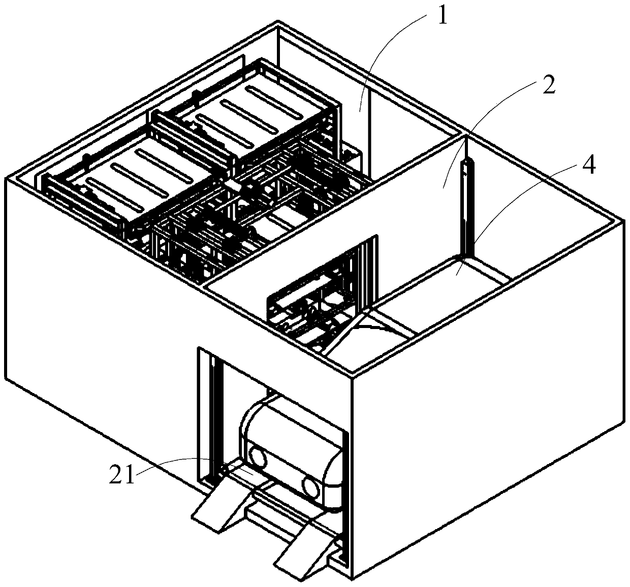
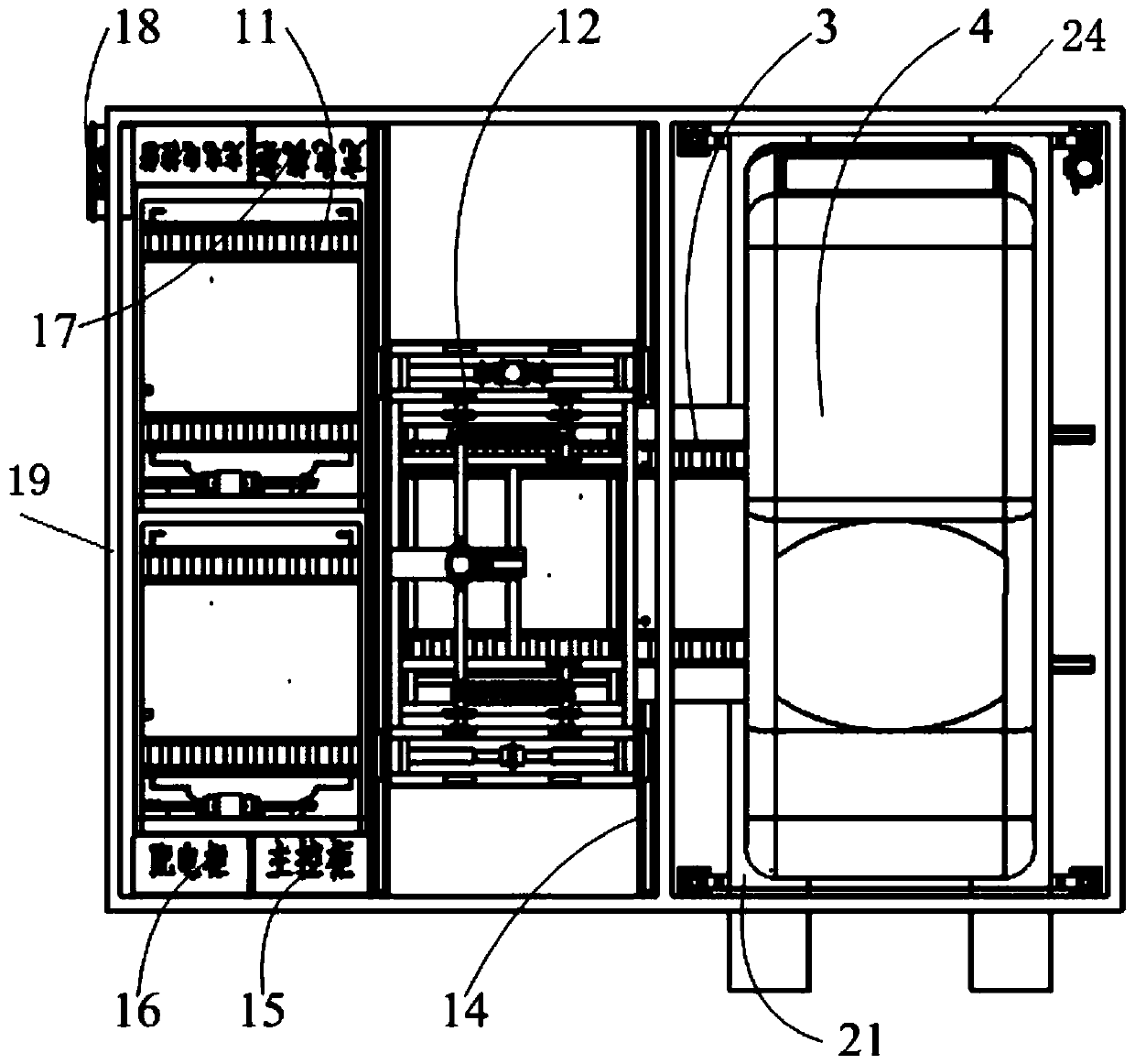
[0036] see figure 1 with figure 2 , an expandable small chassis-type battery-swapping station using a transfer trolley, including a charging container 1, a battery-swapping container 2, and an RGV battery-swapping trolley 3 reciprocating between the charging container 1 and the battery-swapping container 2. The RGV battery exchange trolley 3 can move back and forth between the charging container 1 and the battery exchange container 2, and transports the battery 5 in the electric vehicle 4 back and forth between the electric vehicle 4 and the hoist 12 .

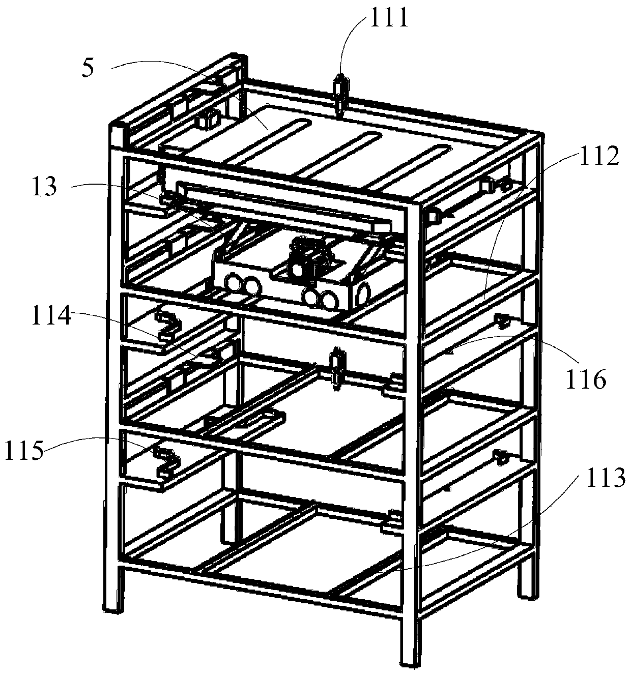
[0037] The charging container 1 includes a first box body 19 and a hoist 12 arranged inside the first box body 19, a transfer trolley 13, a hoist rail 14, a main control cabinet 15, a power distribution cabinet 16, a charging system 17 and a plurality of battery racks 11. A plurality of battery racks 11 are arranged side by side along the length direction of the first box body 19; the hoist track 14 is embedded in the botto...

Embodiment 2

[0050] see Figure 9 , the structure of embodiment 2 is similar to that of embodiment 1, the only difference is that expansion containers 6 are arranged side by side on the outside of charging container 1, and expansion container 6 includes a third box body 62 and extended battery racks arranged side by side in the third box body 62 63 and transition battery rack 61.

[0051] The extension container 6 adopts the transitional battery rack 61 instead of the hoist 12, which can realize the overall flexible expansion of the battery swapping station to meet more battery swapping vehicles. Among them, the transitional battery rack 61 is used for the transfer car 13 to and fro, and the four-way transport battery 5 is between the charging container 1 and the expansion container 6, which realizes the unlimited expansion capability of one transfer car 13 and saves the expansion cost. The structure of the extended battery rack 63 is the same as that of the battery rack 11 .

[0052] Th...


PUM


Abstract

The invention relates to a battery swap station, and especially relates to an expandable small-sized chassis type battery swap station applying a transfer trolley, which resolves the problems of the conventional battery swap station that occupation area is quite large, expanding degree is low, conveying is inconvenient, and fully-automatic power changing cannot be achieved. The expandable small-sized chassis type battery swap station comprises a charging container and a power-changing container, arranged adjacently, and a RGV charging trolley, which conducts reciprocating movement between thecharging container and the power-changing container. The charging container comprises a first case body, and a lifting machine, a transfer trolley, a lifting machine track, a main control cabinet, a power distribution cabinet, a charging system and a plurality of battery racks, with the latter seven being disposed in the first case body. The lifting machine track is embedded in the bottom of the first case body along the length direction. The lifting machine can move along the lifting machine track. The transfer trolley shuttles between a plurality of battery racks and the lifting machine. Oneside of the plurality of battery racks is provided with the main control cabinet and the power distribution cabinet, and the other side is provided with the charging system.

Description

technical field [0001] The invention relates to a substation, in particular to an expandable small chassis type substation using a transfer trolley. Background technique [0002] With the rapid development of society, the shortage of non-renewable energy and environmental pollution have become a problem that continues to be solved. Vehicle exhaust emission is an important factor leading to serious environmental pollution and enhanced greenhouse effect. New energy vehicles have the advantages of low noise, high energy utilization efficiency and no mobile exhaust emissions. Therefore, the development of new energy vehicles has become the general trend. [0003] Pure electric new energy vehicles (hereinafter referred to as electric vehicles) have developed into a leader in new energy vehicles, and how to effectively replenish electric vehicles with insufficient power has become an urgent problem to be solved. At present, the common power supply modes include charging mode and...

Claims


Application Information

Patent Timeline
Patent Type & Authority Applications(China)
IPC IPC(8): B60S5/06B65G35/00
Inventor 刘峥曹青梅林洪怡徐刚张立凌浩
Owner XIAN AEROSPACE PRECISION ELECTROMECHANICAL INST
Why Eureka
Try Eureka