
Cleaning device for columnar supporting part of above water drilling platform

A drilling platform and cleaning device technology, which is applied in the fields of petroleum engineering drilling and foundation engineering drilling, and can solve the problems of corrosion of support parts, potential safety hazards, time-consuming and labor-intensive problems, etc.

Active Publication Date: 2019-05-03
SOUTHWEST PETROLEUM UNIV
View PDF17 Cites 7 Cited by
  • Summary
  • Abstract
  • Description
  • Claims
  • Application Information

AI Technical Summary

Problems solved by technology

However, in the water area where the drilling platform is located, the environmental factors are complex and changeable, and the foundation of the platform is vulnerable to the impact of large underwater undercurrents. There are many, especially the seawater in the sea area is highly corrosive, the amount of microorganisms and suspended mud is large, and the attached microorganisms or molluscs will release certain chemical substances, making the columnar supports inevitably rusted, requiring divers It is time-consuming and labor-intensive to often go underwater to check, and the underwater situation is difficult to monitor, which is likely to bring safety hazards
Furthermore, in deep waters, the drilling platform needs to be raised and lowered reasonably according to the change of water depth, and the support is an important supporting part and track for the drilling platform to rise and fall independently. When there are too many attachments on the outer wall of the support, it will cause drilling Reduced lifting flexibility of the platform

Method used


Image

  • Cleaning device for columnar supporting part of above water drilling platform
  • Cleaning device for columnar supporting part of above water drilling platform
  • Cleaning device for columnar supporting part of above water drilling platform

Examples


Embodiment 1

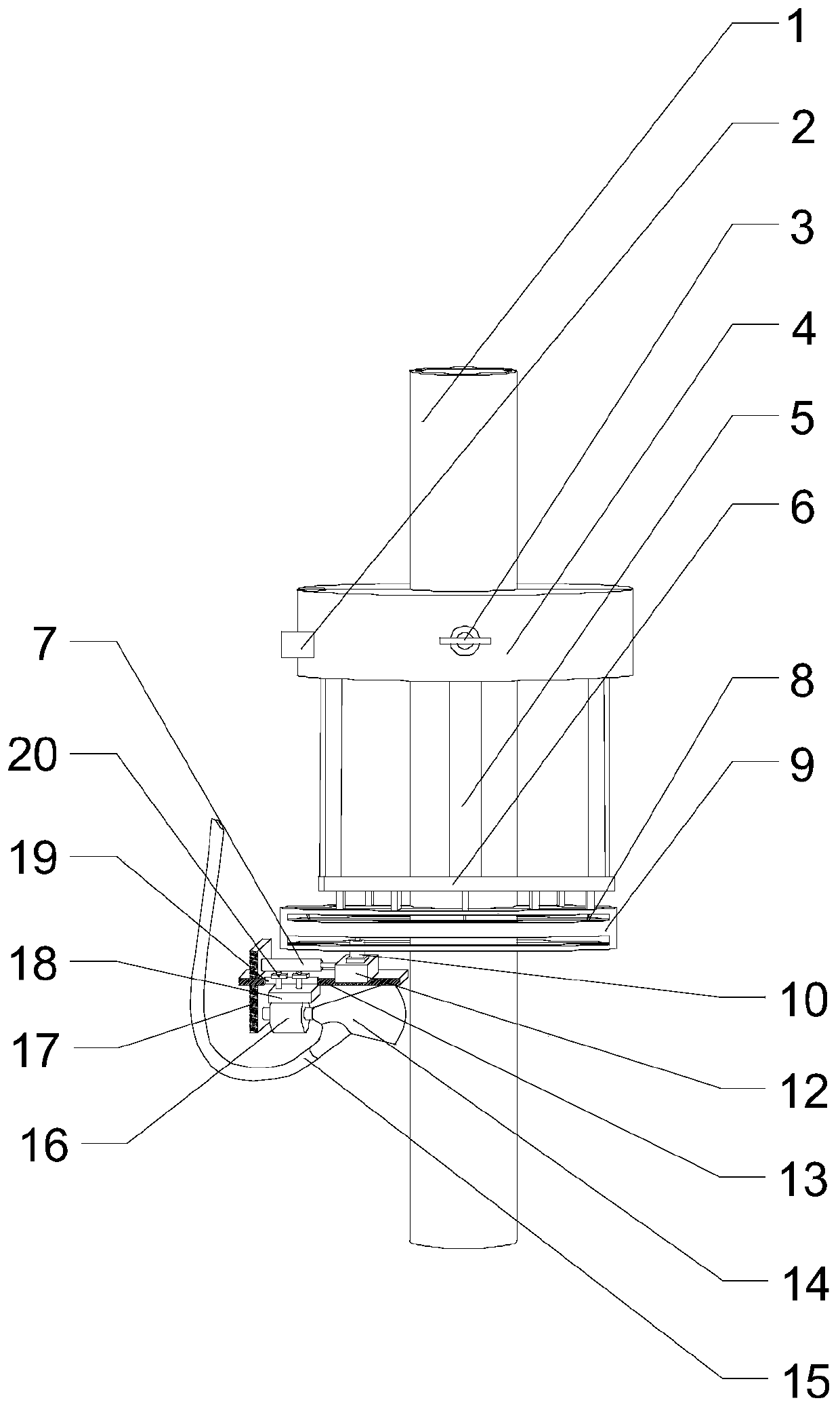
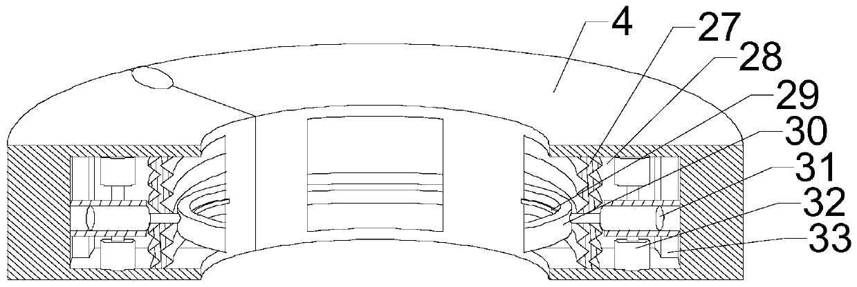
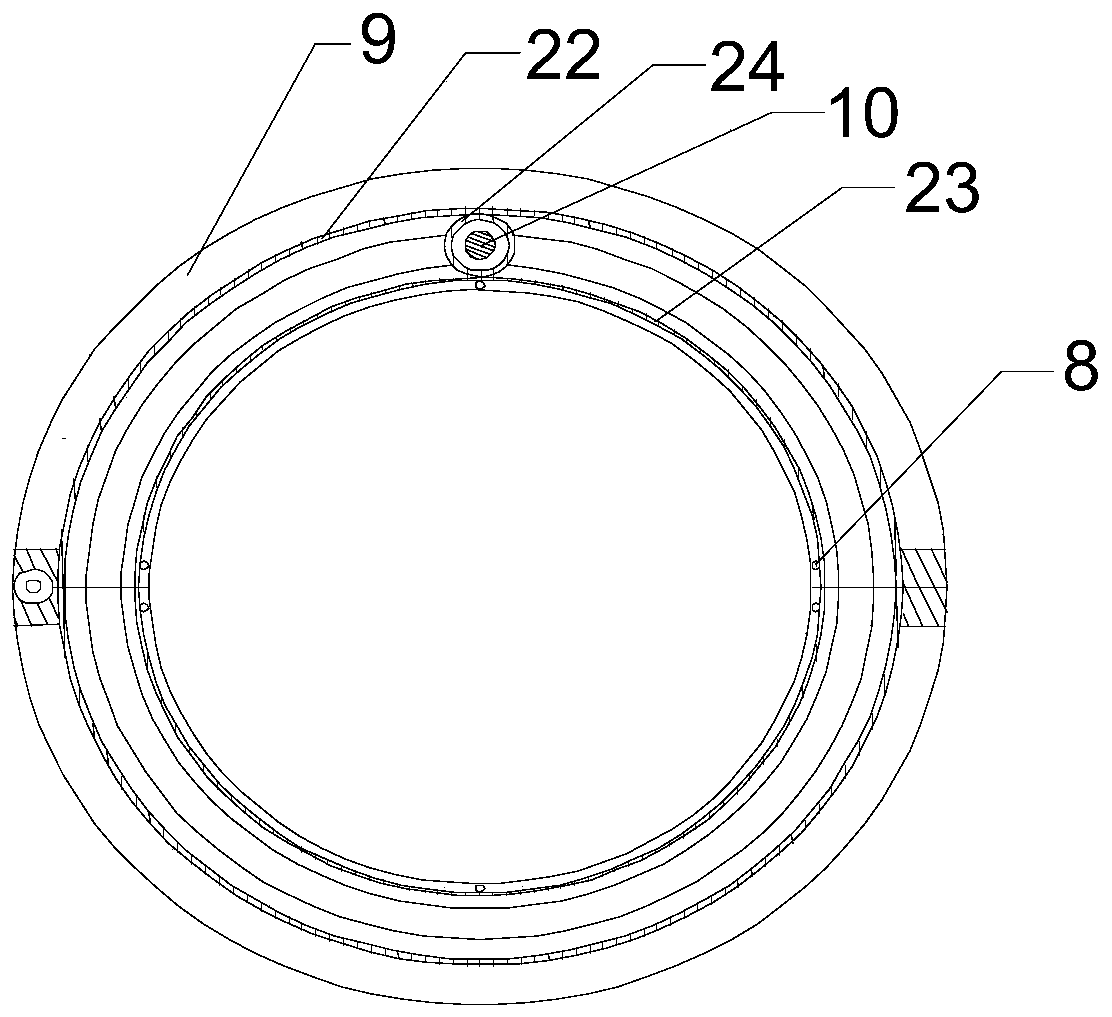
[0030] Such as Figure 1-5 As shown, this embodiment includes clamping units sleeved on the outer peripheral wall of the support 1, and each clamping unit includes a semicircular traveling cylinder 4 and an orbital ring 9, and the orbital ring 9 is fixed on the traveling cylinder 4 The lower end surface of the track ring 9 is provided with a semicircular flange on its inner peripheral wall along the circumferential direction of the orbit ring 9. An external toothed belt 22 is installed on the upper end surface of the flange. Circular inner ring, and the radius of the circle corresponding to the inner ring is smaller than the radius of the circle corresponding to the flange, an inner toothed belt 23 is provided on the upper surface of the inner ring, and a support seat 12 is provided under the track ring 9, and the rotating motor 10 is arranged on the supporting seat 12, the output end of the rotating electrical machine 10 extends upwards after passing through the gap between t...

Embodiment 2

[0037] Such as Figure 1~3 As shown, in this embodiment, on the basis of Embodiment 1, a guide groove 33 perpendicular to the axis of the support member 1 is formed on the inner wall of each arc-shaped groove 28, and the end of the rectangular cylinder is slidably arranged In the guide groove 33; on the inner peripheral wall of each snap ring 30, a matching arc-shaped rubber corrugated strip 29 is provided; on the lower end surface of each traveling cylinder 4, a plurality of support rods are provided 5. The semicircular bottom ring 6 is connected to the lower ends of a plurality of support rods 5, the upper end surface of the track ring 9 is connected to the bottom ring 6 through a connecting rod, and a semicircular fixing ring is provided on the outer wall of the connecting rod , the inner ring is connected with the fixed ring through the connecting rod 8 .

[0038] In this embodiment, during the linear movement of the lifting unit, the rectangular cylinder in the arc-shape...

Embodiment 3

[0042] Such as Figure 1-5 Shown, present embodiment is on the basis of embodiment 2, and described cleaning assembly comprises movable plate 13, vertical plate 17 and hanging plate 18, is fixed with propelling cylinder 21 on the side wall of vertical plate 17, and propelling cylinder 21 The output end is connected with the supporting seat 12, and a through hole is opened in the middle part of the vertical plate 17, and one end of the movable plate 13 extends outward after moving through the through hole, and the other end of the movable plate 13 faces the support member 1, and the The lower surface of the supporting seat 12 is connected with the upper surface of the movable plate 13, a rectangular hole 19 is provided on the movable plate 13, and at least one strut is provided at the bottom of the propelling cylinder 21, and the clamping plate 7 is installed on the strut, and the clamping plate 7 Place on the upper surface of the movable plate 13 and the width of the clamping ...


PUM


Abstract

The invention discloses a cleaning device for a columnar supporting part of an above water drilling platform. The cleaning device comprises two clamping units, wherein each clamping unit comprises a traveling cylinder and a track ring, the track rings are fixed to the lower end surfaces of the traveling cylinders, flanges are arranged on the inner circumferential walls of the track rings in the circumferential directions of the track rings, outer tooth belts are installed on the upper end surfaces of the flanges, semicircular inner rings are further arranged below the traveling cylinders, inner tooth belts are arranged on the upper surfaces of the inner rings, and supporting seats are arranged below the track rings; and rotating motors are arranged on the supporting seats, the output endsof the rotating motors extend upwards after penetrating through gaps between the flanges and the inner rings, rotating gears are installed at the tail ends of the extension sections of the output endsof the rotating motors, the rotating gears are correspondingly matched with the outer tooth belts and the inner tooth belts, and cleaning assemblies are arranged on the lower surfaces of the supporting seats. Aiming at the defects in the prior art, the cleaning device can regularly clean attachments of the supporting part immersed in seawater, the damage probability of the supporting part is reduced, and the service life of the drilling platform is further improved.

Description

technical field [0001] The invention relates to the fields of basic engineering drilling, petroleum engineering drilling and the like, and in particular relates to a cleaning device for a columnar support of a water drilling platform. Background technique [0002] At present, more than 100 countries and regions in the world are conducting oil and gas exploration offshore, and more than 40 countries and regions are exploiting more than 150 offshore oil and gas fields. 25% of the total volume, while drilling or drilling platforms are widely used in offshore oil and gas exploitation; at the same time, both in the field of geological exploration and in the construction of bridges, towers and other lines, it is necessary to drill the waters of the passage. In order to carry out pile foundation construction, a drilling platform is also required. The drilling platform is a professional operating platform mainly used for drilling in water areas. However, in the water area where the...

Claims


Application Information

Patent Timeline
Patent Type & Authority Applications(China)
IPC IPC(8): E21B15/02E02B17/00B08B9/023
Inventor 郭亮居晨郭辉钱德良张军伟裴春曲宏略刘壮志徐凯
Owner SOUTHWEST PETROLEUM UNIV
Learn More