Novel noise reduction worm tongue structure for centrifugation

A volute tongue and a new type of technology are applied in the field of new noise reduction volute and tongue structures for centrifugal use, which can solve the problems of structural improvement of the outer layer and inner layer, limited noise reduction effect of centrifugal fans, and high manufacturing cost, and achieve uniform pressure and reduce The effect of pressure pulsation, reduction of rotating noise

Active Publication Date: 2019-05-03
FANS TECH ELECTRIC CO LTD
View PDF7 Cites 4 Cited by
  • Summary
  • Abstract
  • Description
  • Claims
  • Application Information

AI Technical Summary

Problems solved by technology

This patent only sets through holes in the arc portion of the volute tongue, and does not further improve the structure of the outer layer and inner la

Method used


Image

  • Novel noise reduction worm tongue structure for centrifugation
  • Novel noise reduction worm tongue structure for centrifugation
  • Novel noise reduction worm tongue structure for centrifugation

Examples


Embodiment 2

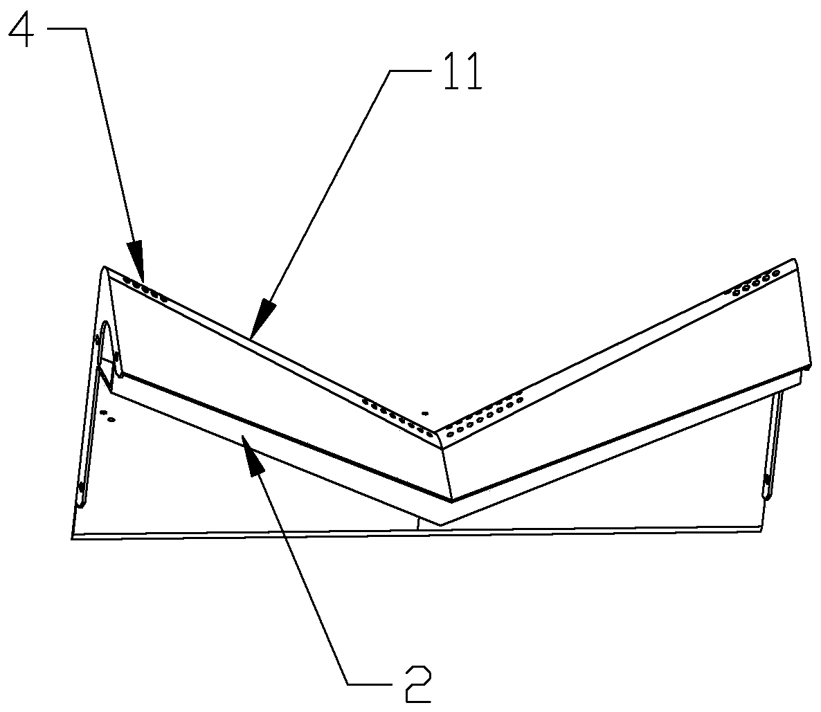
[0050] Such as figure 2 As shown, this embodiment only describes the difference from the above embodiment, and the rest of the technical features are the same as the above embodiment. In this embodiment, the through-holes 4 are distributed continuously and equidistantly from the left end to the right end of the bent portion 1 . The position and shape of the through hole 4 are designed differently according to different fans. The design is combined with the gas flow conditions near the volute tongue and the shape of the cavity to optimize the design. When the optimal design is obtained, the acoustic performance of the fan will be the best. aerodynamic performance.

Embodiment 3

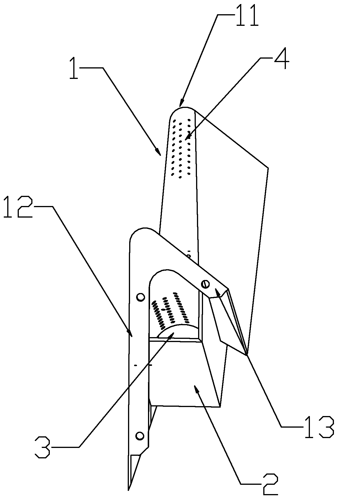
[0052] Such as Figure 4 As shown, this embodiment only describes the difference from the above embodiment, and the rest of the technical features are the same as the above embodiment. In this embodiment, the bottom of the cavity wall 2 is a corrugated structure 21 , and the corrugated structure 21 includes several crests and troughs arranged along the direction from the left end to the right end of the cavity wall 2 . When the air flow from the impeller flows to the position near the volute tongue, part of the air flow enters the cavity structure 3 from the through hole on the high pressure side of the volute tongue. After the air flow flows in the cavity structure 3 with a wave-shaped bottom, 3. The through holes on the low pressure side of the volute tongue on both sides flow out, and the wave-shaped cavity regulates the air intake state of the through hole 4 to a certain extent. The volute tongue with the through hole 4 absorbs part of the gas in the vicinity of the volute...

Embodiment 4

[0054] Such as Figure 5 As shown, this embodiment only describes the difference from the above embodiment, and the rest of the technical features are the same as the above embodiment. In this embodiment, the volute tongue structure is a flat tongue structure, and the bending part 1 of the flat tongue structure extends in a straight line from the left end to the right end, and the bending part 1 of the flat tongue structure is from the left end to the right end. Horizontal or inclined in one direction, the cavity wall 2 is a horizontal bottom wall or a bent wall, and the two end surfaces of the bent wall along the width direction are connected to the inner surface of the bent part 1 . The direction from left to right is the length direction of the bent wall, and the direction perpendicular to the length direction is the width direction. The horizontal bottom wall or the bottom of the bent wall is a wave-shaped structure or a horizontal structure.


PUM


Abstract

The invention discloses a novel noise reduction worm tongue structure for centrifugation. The worm tongue structure comprises a worm tongue main body, and a cavity structure positioned under the wormtongue main body; the worm tongue main body comprises a worm tongue bent part, and a cavity wall positioned under the bent part; the inner side surface of the worm tongue bent part is connected with the end surface of the cavity wall to form a cavity structure; the left and right ends of the worm tongue bent part are connected with outlet side walls of a worm shell; the left and right ends of thecavity wall and the outlet side walls of the worm shell form a closed cavity; and a through hole is formed in the bent place of the worm tongue bent part. A noise reduction worm tongue through hole ismatched with the cavity structure to precisely control the flowing of air near the worm tongue to balance the flow distribution of air currents near the worm tongue in an outlet of a fan and the pressure distribution of the air currents near a low-pressure side, so that the pressure of the air currents near the worm tongue is more uniform, the pressure pulsation is reduced, and the rotating noiseis lowered; and meanwhile, the air currents near the worm tongue are adjusted through the through hole, so that eddy currents near the worm tongue can be reduced, and the eddy noise of the fan is lowered.

Description

technical field [0001] The invention relates to the field of fans, in particular to a novel noise-reducing volute tongue structure for centrifugal use. Background technique [0002] In the ventilation industry, the design of the volute tongue structure in traditional fans is simple, most of which are closed volute tongue structures. The high-speed and high-pressure airflow sent by the centrifugal impeller hits the volute tongue, and the air at the volute tongue will have periodic pressure and velocity. Pulsation produces high aerodynamic noise and pollutes the environment. For equipment with high noise requirements such as air conditioners and other products, the aerodynamic noise generated by the air near the volute tongue may also cause obvious howling sound of the equipment and reduce the sound quality. The existing centrifugal fan noise reduction volute tongue structure design in the industry requires a very complex structural cavity. Its design and optimization require ...

Claims


Application Information

Patent Timeline
IPC IPC(8): F04D29/42F04D29/66
Inventor 袁小永
Owner FANS TECH ELECTRIC CO LTD
Why Eureka
Try Eureka