
Rotor liquid cooling system structure suitable for inner rotor motor

An internal rotor motor and system structure technology, applied in the field of motor cooling system and rotor liquid cooling system structure, can solve the problems of motor heating, temperature rise, damage insulation, narrow application range, etc., to improve power density, increase electromagnetic load, cost reduction effect

Inactive Publication Date: 2019-05-03
HARBIN UNIV OF SCI & TECH
View PDF4 Cites 4 Cited by
  • Summary
  • Abstract
  • Description
  • Claims
  • Application Information

AI Technical Summary

Problems solved by technology

[0002] The loss generated during the operation of the motor will cause heat generation, and the temperature rise will damage the insulation or accelerate aging
Copper consumption of the rotor, mechanical loss caused by rotation, friction loss of the shaft extension, serious heat generation of the rotor, which needs to be dissipated through the stator casing through the air gap, and the heat dissipation performance is poor. Therefore, in order to improve the performance and output power of the motor, it is necessary to improve the motor cooling conditions, the existing motor cooling methods are usually natural cooling, forced air cooling, wind-air cooling, air-water cooling and water cooling, among which the liquid-filled water cooling directly acts on the heating part of the motor and has high cooling efficiency. It is usually used in Coal mining, but the traditional liquid-filled cooling method has a narrow application range, which will affect the mechanical properties of the motor and affect the heat dissipation effect

Method used


Image

  • Rotor liquid cooling system structure suitable for inner rotor motor
  • Rotor liquid cooling system structure suitable for inner rotor motor
  • Rotor liquid cooling system structure suitable for inner rotor motor

Examples


Embodiment Construction

[0032] Embodiments of the present invention will be further described in conjunction with the accompanying drawings.

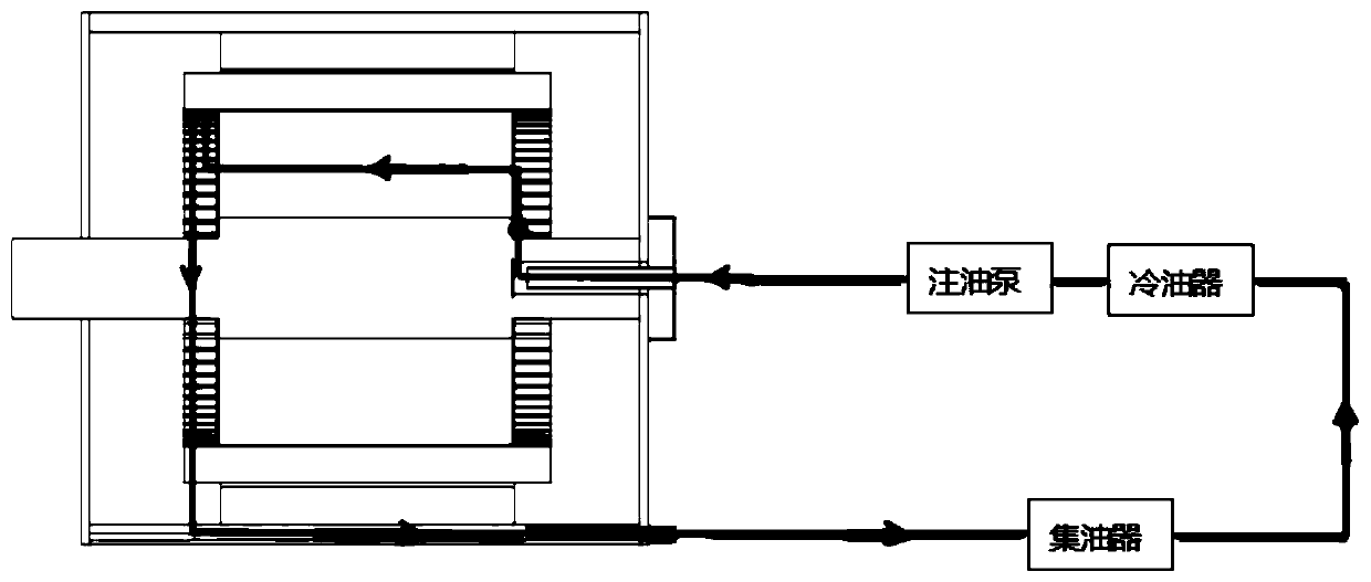
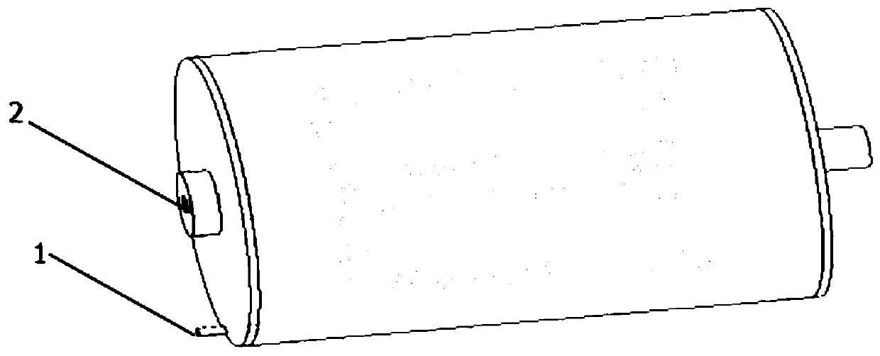
[0033] A rotor liquid cooling system structure suitable for an inner rotor motor in this embodiment includes an external circulation part and an inner cooling part. The inner rotor motor includes a rear end cover, an inner rotor 16 and a rotating shaft 17 inserted into the inner rotor, The rear end cover is provided with a rear end cover liquid inlet 2 and a rear end cover liquid outlet 1, and the two ends of the rotating shaft 17 extend outward to the outside of the inner rotor 16, one side of the rotating shaft 17 is the liquid inlet, and the other The side is the liquid outlet, and at least one liquid inlet channel 5 is opened on the rotating shaft 17 of the liquid inlet end, and a number of radial guide channels 10 are opened on the rotating shaft 17 inside the inner rotor 16, and a number of axial liquid passages are opened on the inner rotor 16. The hole...


PUM


Abstract

The invention discloses a rotor liquid cooling system structure suitable for an inner rotor motor, and belongs to the field of motors. The invention aims at solving the problems that in the prior art,heat in a motor is difficult to dissipate, and the cooling effect is poor. A liquid incoming end is arranged at one side of a rotating shaft, and the other side is provided with a liquid outgoing end. At least one liquid incoming channel is formed on the rotating shaft at the liquid incoming end, and a plurality of radial flow guide channels are formed on the rotating shaft in the inner rotor. Aplurality of axial liquid through holes are formed in the inner rotor. The liquid incoming channel and the radial flow guide channel are communicated with the axial liquid through holes, and an outputend of an external circulation part is connected with the liquid incoming pipe. Cooling liquid in the liquid incoming pipe is conveyed to the axial liquid through holes through the radial flow guidechannels, and the cooling liquid flows to the liquid outgoing end along the axial liquid through holes and is sprayed to an extending end of the rotor winding through a centrifugal force and then is collected through the external circulation part. The structure is suitable for any inner rotor motor, and the heat dissipation effect is good.

Description

technical field [0001] A motor cooling system relates to the field of motors, in particular to a rotor liquid cooling system structure suitable for inner rotor motors. Background technique [0002] The loss generated during the operation of the motor will cause heat generation, and the temperature rise will damage the insulation or accelerate aging. Copper consumption of the rotor, mechanical loss caused by rotation, friction loss of the shaft extension, serious heat generation of the rotor, which needs to be dissipated through the stator casing through the air gap, and the heat dissipation performance is poor. Therefore, in order to improve the performance and output power of the motor, it is necessary to improve the motor cooling conditions, the existing motor cooling methods are usually natural cooling, forced air cooling, wind-air cooling, air-water cooling and water cooling, among which the liquid-filled water cooling directly acts on the heating part of the motor and h...

Claims


Application Information

Patent Timeline
IPC IPC(8): H02K1/32H02K9/19
Inventor 徐永明陈宣瑞艾萌萌韩坤
Owner HARBIN UNIV OF SCI & TECH
Learn More