Method and system for suppressing torque ripple of brushless DC motor

A technology of brush DC motor and torque ripple, which is applied in the direction of torque ripple control, etc., can solve the problems of high cost, low control efficiency, and inconspicuous torque ripple suppression, and achieve better suppression of torque ripple Effect

Active Publication Date: 2019-05-03
WUHAN INSTITUTE OF TECHNOLOGY
View PDF12 Cites 5 Cited by
  • Summary
  • Abstract
  • Description
  • Claims
  • Application Information

AI Technical Summary

Problems solved by technology

However, the existing PWM chopping method has the following defects: the control efficiency is low, the dead time needs to be added and the suppression of torque ripple is not obvious due to the addition of the dea

Method used


Image

  • Method and system for suppressing torque ripple of brushless DC motor
  • Method and system for suppressing torque ripple of brushless DC motor
  • Method and system for suppressing torque ripple of brushless DC motor

Examples


Embodiment 1

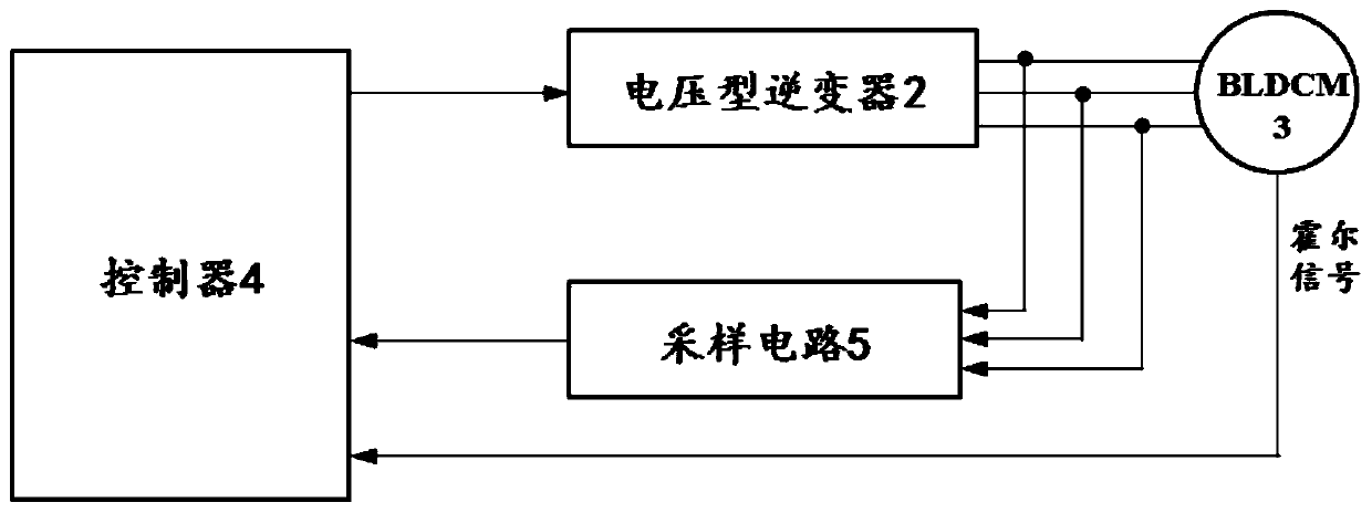
[0070] Embodiment one, as figure 1 As shown, a brushless DC motor torque ripple suppression system includes a voltage source inverter 2, a controller 4 and a sampling circuit 5;

[0071] The voltage-type inverter 2 is used to control the opening and closing of each phase of the brushless DC motor 3;

[0072] The sampling circuit 5 is used to collect the three-phase phase current during the operation of the brushless DC motor 3, and send the collected three-phase phase current to the controller 4;

[0073] The controller 4 is used to receive the three-phase phase current and the Hall signal collected by the Hall sensor of the brushless DC motor 3; Whether the brushless DC motor 3 is in the commutation state, when the judgment result is no, adopt the two-two conduction control mode to control the voltage type inverter, and when the judgment result is yes, use the two-two conduction and three-three The conduction switching control mode controls the voltage source inverter.

[...

Embodiment 2

[0140] Embodiment two, such as Figure 7 Shown, a kind of suppression method of brushless DC motor torque ripple, it adopts the suppression system of brushless DC motor torque ripple of the present invention, comprises the following steps:

[0141] S1: Obtain the Hall signal collected by the Hall sensor in the brushless DC motor and the three-phase phase current during the operation of the brushless DC motor, and according to the Hall signal and the The three-phase phase current determines whether the brushless DC motor is in the commutation state, if not, enters S2, and if so, enters S3;

[0142] S2: controlling the voltage source inverter by using the pairwise conduction control method;

[0143] S3: Controlling the voltage source inverter by using the two-two conduction and three-three conduction switching control mode.

[0144] In the commutation stage, the two-two conduction control method is adopted first. Since the current of the inductance cannot change suddenly in th...


PUM


Abstract

The invention relates to a method and system for suppressing torque ripple of a brushless DC motor. The method comprises the steps: acquiring Hall signals collected by a Hall sensor in the brushless DC motor and a three-phase phase current in the operation process of the brushless DC motor, judging whether the brushless DC motor is in a phase change state or not according to the Hall signals and the three-phase phase current: if not, controlling a voltage type inverter in a two-two conduction control mode, or else controlling the voltage type inverter in a two-two conduction and three-three conduction switching control mode. At the commutation stage, only one switching tube is changed through the two-two conduction and three-three conduction switching control mode, and the torque ripple generated by the brushless DC motor in commutation is effectively restrained. Due to the fact that the two-two conduction control mode and the three-three conduction control mode are matched with each other, a dead zone does not need to be set, the suppressing effect of torque ripples is better, the detection method and the control algorithm are simpler, the calculation difficulty is lower, the costis lower, and the control efficiency is higher.

Description

technical field [0001] The invention relates to the technical field of motor control, in particular to a method and system for suppressing torque ripple of a brushless DC motor. Background technique [0002] After years of development, motors have been used in all aspects of modern society. DC motors are increasingly used in electric drive systems due to their excellent regulation and start-up performance. Brushless DC motors are developed on the basis of brushed DC motors. my country's reserves of permanent magnet materials are very rich, so it has laid a good material foundation for the development of brushless DC motors. Due to the maturity of the processing level of permanent magnet materials and the improvement of control circuit technology, brushless DC motors have been widely used in various fields and links of modern society and national economy. Brushless DC motors have the advantages of simple structure, high power density, and long service life, so they are wid...

Claims


Application Information

Patent Timeline
IPC IPC(8): H02P6/10
Inventor 李自成孔庆尧王后能曾丽熊涛
Owner WUHAN INSTITUTE OF TECHNOLOGY
Why Eureka
Try Eureka