
An imaging control circuit of a multipurpose space camera and the multipurpose space camera

A space camera and imaging control technology, applied in TV, electrical components, color TV, etc., can solve problems affecting image quality, difficult to avoid adjacent CCD coupling noise, large thermal noise, etc., to reduce inter-chip crosstalk, reduce Effects of Thermal Noise and Reliability Improvement

Active Publication Date: 2019-05-03
CHANGCHUN INST OF OPTICS FINE MECHANICS & PHYSICS CHINESE ACAD OF SCI
View PDF7 Cites 2 Cited by
  • Summary
  • Abstract
  • Description
  • Claims
  • Application Information

AI Technical Summary

Problems solved by technology

However, according to the requirements, TDI CCDs are often required to work at a higher line frequency, which leads to a certain high-frequency coupling between the spliced ​​TDI CCDs, and this coupling will be manifested in the final image. thereby affecting the quality of the image
The multiple TDI CCDs of traditional space cameras share a set of processing circuits, which makes it difficult to avoid coupling noise between adjacent CCDs. At the same time, due to the sharing of a set of processing circuits, the power consumption of multiple spliced ​​CCDs will also be concentrated in one set. processing circuitry, so thermally noisy

Method used


Image

  • An imaging control circuit of a multipurpose space camera and the multipurpose space camera
  • An imaging control circuit of a multipurpose space camera and the multipurpose space camera
  • An imaging control circuit of a multipurpose space camera and the multipurpose space camera

Examples


Embodiment 1

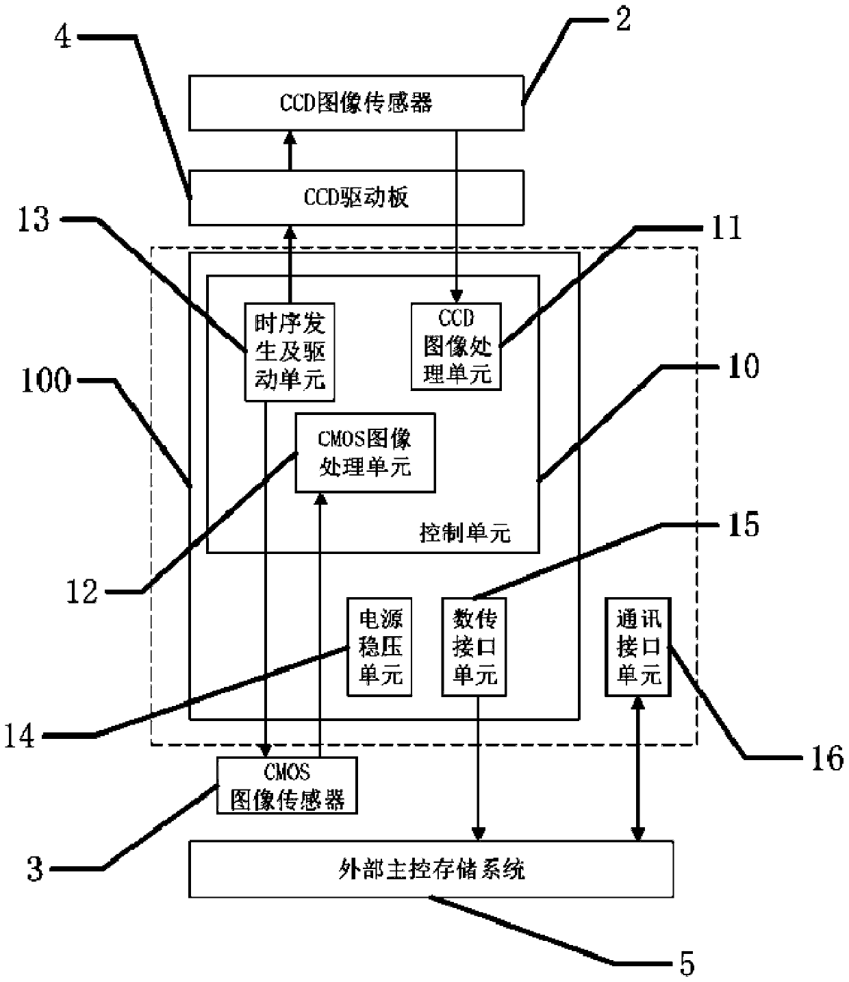
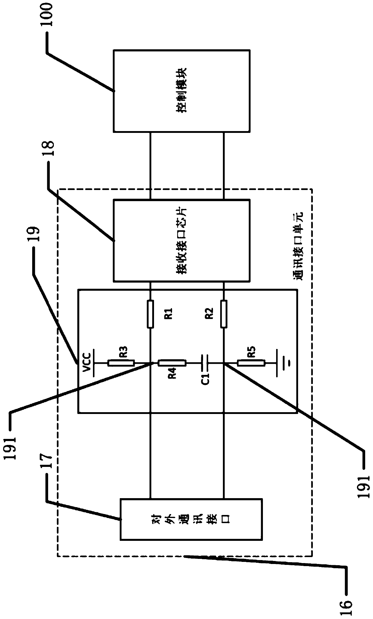
[0034] figure 1 It is a schematic structural diagram of the imaging control circuit of the multi-purpose space camera in Embodiment 1 of the present invention. Such as figure 1 As shown, Embodiment 1 of the present invention provides an imaging control circuit for a multi-purpose space camera, which includes a communication interface unit 16 and a control module 100 , and the control module 100 communicates through the communication interface unit 16 .

[0035] The control module 100 includes a control unit 10 and a data transmission interface unit 15 . The control unit 10 transmits image data to the outside through the data transmission interface unit 15 .

[0036] The control unit 10 is an FPGA control unit, which includes a CCD image processing unit 11 , a CMOS image processing unit 12 and a timing generation and driving unit 13 . The timing generating and driving unit 13 is electrically connected to the CCD image sensor 2 and the CMOS image sensor 3 respectively. The t...

Embodiment 2

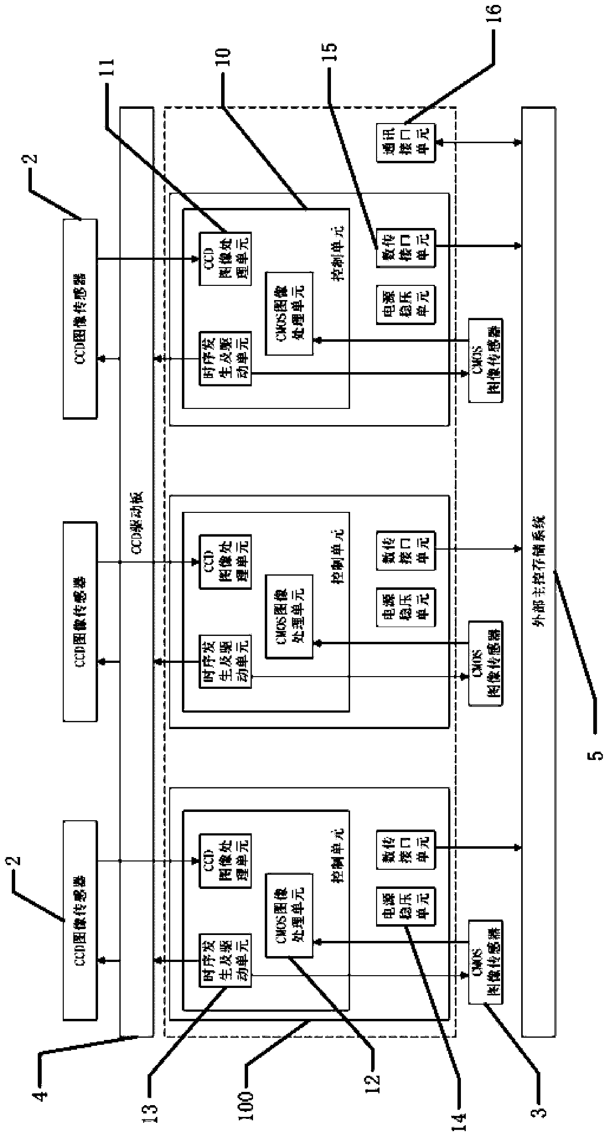
[0050] image 3 It is a schematic structural diagram of the imaging control circuit of the multi-purpose space camera in Embodiment 2 of the present invention. Such as image 3 As shown, Embodiment 2 of the present invention provides an imaging control circuit for a multi-purpose space camera, which includes a communication interface unit 16 and several control modules 100, and several control modules 100 share the communication interface unit 16 for external communication.

[0051] In this embodiment, preferably, the number of control modules 100 is three, and each control module 100 is independently connected to the corresponding CCD image sensor 2 and CMOS image sensor 3 . The number of CCD image sensors 2 and CMOS image sensors 3 matches the number of control modules 100 .

[0052] The control module 100 cooperates with the correspondingly connected CCD image sensor 2 and CMOS image sensor 3 , and several control modules 100 work independently without interfering with ea...


PUM


Abstract

The invention provides an imaging control circuit of a multipurpose space camera and the multipurpose space camera. The imaging control circuit comprises at least two control modules, and each controlmodule is used for independently controlling a corresponding CCD image sensor and a corresponding CMOS image sensor; The control module comprises a control unit and a data transmission interface unit; the control unit comprises a CCD image processing unit and a CMOS image processing unit, and the CCD image processing unit and the CMOS image processing unit respectively process and integrate the digital image data transmitted by the CCD image sensor and the CMOS image sensor to generate parallel data; And the data transmission interface unit converts the parallel data into LVDS signals for transmission. The beneficial effects of the invention are that each CCD is provided with a set of independent processing circuit, the shooting parameters of each detector can be set, the crosstalk between chips can be reduced to the maximum extent, and the imaging signal-to-noise ratio is improved. And the multi-path independent control circuit improves the reliability and reduces the overload problem caused by sharing the processing circuit.

Description

technical field [0001] The invention relates to the technical field of electronic applications, in particular to an imaging control circuit of a multi-occasion and multi-purpose space camera for space detection, and also relates to a multi-purpose space camera with the imaging control circuit. Background technique [0002] China currently refers to space exploration activities on celestial bodies beyond the earth as deep space exploration. With the improvement of the level and capability of human spaceflight technology, the concept of deep space exploration will gradually develop. In other words, the technological development in the field of deep space exploration and the connotation of the concept of deep space exploration are mutually reinforcing. [0003] Deep space exploration refers to the exploration of breaking away from the gravitational field of the earth and entering the space of the solar system and space. Then, naturally, the devices performing deep space explora...

Claims


Application Information

Patent Timeline
Patent Type & Authority Applications(China)
IPC IPC(8): H04N5/369H04N5/372H04N5/374H04N5/232H04N5/217H04N5/225
Inventor 周鹏骥王晓东刘文光黄敬涛
Owner CHANGCHUN INST OF OPTICS FINE MECHANICS & PHYSICS CHINESE ACAD OF SCI
Learn More