Vehicle door outside handle device, vehicle door, and vehicle
A handle and vehicle technology, applied to vehicle locks, printing devices, vehicle parts, etc., can solve problems such as the inability to achieve the side mirror function, achieve the effect of ensuring rear visibility and improving design
- Summary
- Abstract
- Description
- Claims
- Application Information
AI Technical Summary
Problems solved by technology
Method used
Image


Examples
no. 1 example
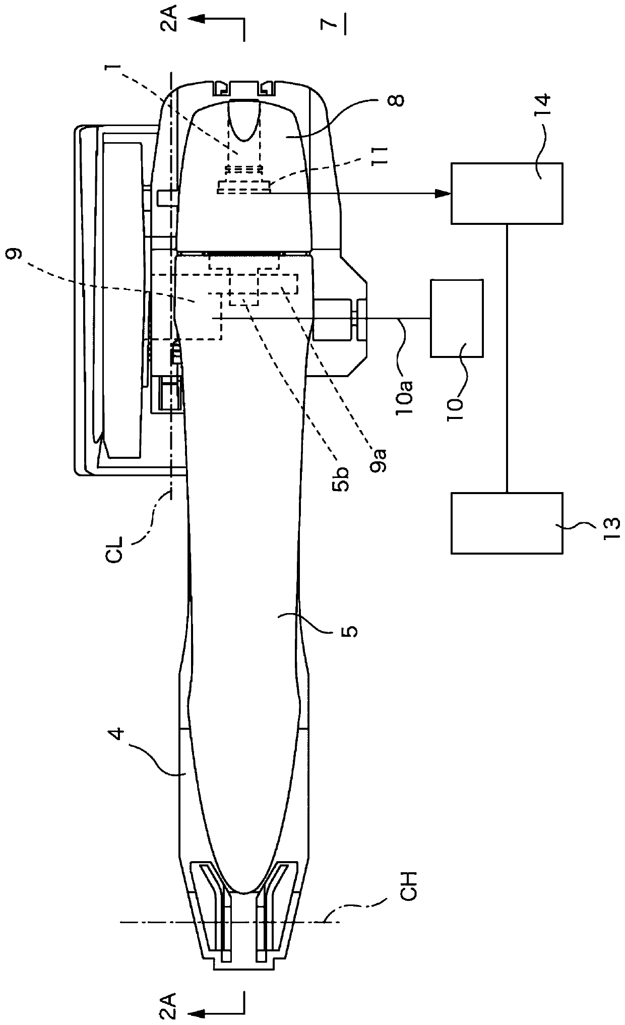
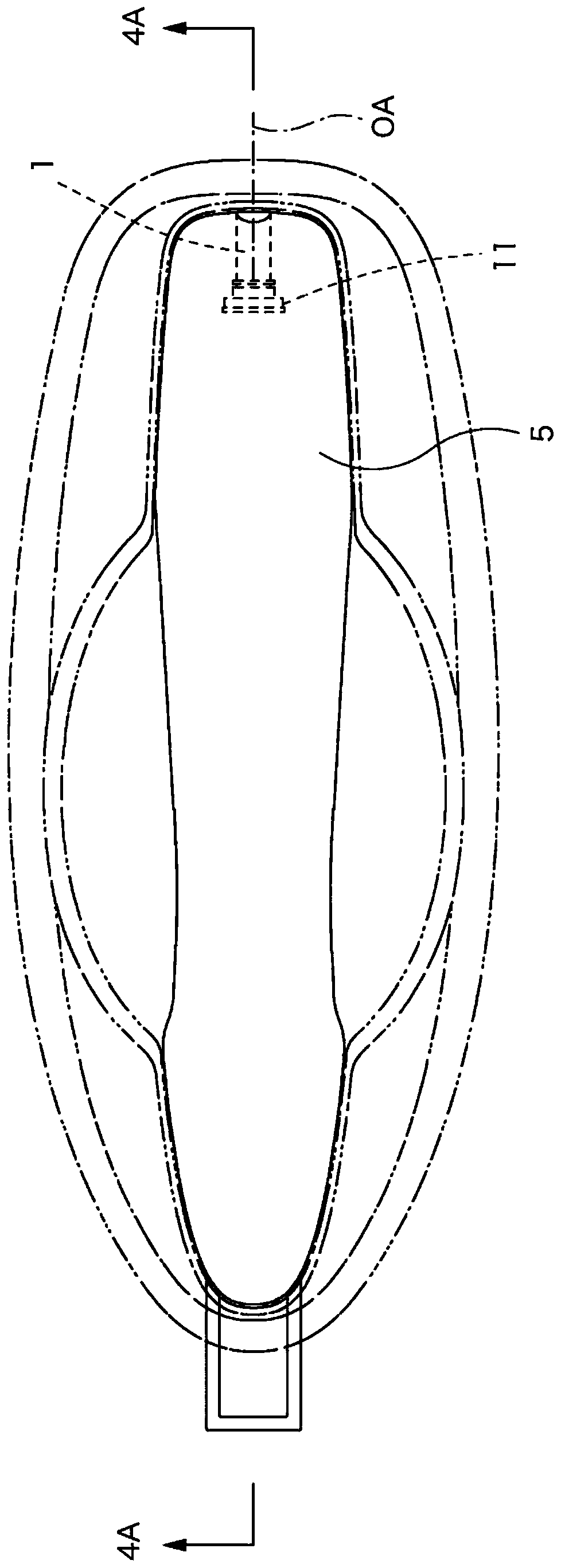
[0043] Figure 1 to 2 (c) shows the first embodiment of the present disclosure. The outside handle according to the present embodiment includes a handle base 4 fixed along the rear surface of the door panel 7 constituting the side wall of the vehicle, and a handle body 5 connected to the handle base 4.
[0044] The hinge protrusion 5 a is provided at the front end of the handle body 5. After the hinge protrusion 5 a is inserted into the door, the handle body 5 slides forward to be connected to the handle base 4. The stopper 8 is installed to the handle base 4 so as to maintain the connected state by adjusting the backward sliding of the handle body 5 installed as described above.
[0045] In the state where the handle body 5 is connected to the handle base 4, when the handle body 5 is removed from figure 2 When the initial positions shown in (a) to 2(c) rotate around the center of rotation (CH) in the direction of the arrow RH, the protrusion 9a of the relay lever 9 passes throu...
no. 2 example
[0061] Figure 5 (a) to 5(c) and 6(a) to 6(c) show the second embodiment of the present disclosure. In this embodiment, the imaging module 11 is configured to be rotatable, and the imaging module 11 is fixed to a module housing 17 having a cylindrical shape and opening backward. Such as Figure 5 As shown in (b), a module accommodating recess 17a opened backward is formed in the module housing 17, and the Figure 5 The left side in (b) is fitted into the module accommodating recess 17a to mount the imaging module 11.
[0062] The module housing 17 in which the imaging module 11 is embedded is connected to the unit base 18 to constitute a camera unit 19. In the unit base 18, a pair of hinge fins 18b stand upright from the base plate 18a. The above-mentioned module housing 17 is rotatably connected to the unit base 18 by fitting the shaft portions 17 b protruding on both side walls into the bearing recesses 18 c of the hinge flap 18 b.
[0063] In addition, the motor 20 is fixed to...
no. 3 example
[0071] Figure 7 , 8 (a) and 8(b) show the third embodiment of the present disclosure. versus figure 1 Similar to the embodiment shown in the embodiment, the outer handle device of this embodiment is formed by connecting the handle body 5 to the handle base 4 fixed to the back of the door panel 7. When the handle body 5 rotates around the rotation center (CH), the protrusion of the relay lever 9 is pulled out to the surface side by operating the stepped portion 5b to rotate the relay lever 9, and then the door latch is operated via the cable device 10a 装置10。 Device 10.
[0072] In this embodiment, the mirror 6 that requires a relatively small installation volume is arranged in the handle body 5, and the imaging module 11 that requires a large volume is arranged on the handle base 4 side.
[0073] In this example, a prism is used as the mirror 6 and is fixed to the mirror seating surface 5 e formed in the innermost part of the through hole 1. In order to prevent dust from entering ...
PUM
 Abstract
Description
Claims
Application Information
 - R&D
- Intellectual Property
- Life Sciences
- Materials
- Tech Scout
- Unparalleled Data Quality
- Higher Quality Content
- 60% Fewer Hallucinations
Browse by: Latest US Patents, China's latest patents, Technical Efficacy Thesaurus, Application Domain, Technology Topic, Popular Technical Reports.
© 2025 PatSnap. All rights reserved.Legal|Privacy policy|Modern Slavery Act Transparency Statement|Sitemap|About US| Contact US: help@patsnap.com