Container and biogas installation

A biogas and container technology, applied in the field of containers, can solve the problems of equipment consumption, high investment costs and high operating costs, and achieve the effect of reducing operating costs

Active Publication Date: 2019-05-03
BIOENERGY CONCEPT GMBH
View PDF10 Cites 0 Cited by
  • Summary
  • Abstract
  • Description
  • Claims
  • Application Information

AI Technical Summary

Problems solved by technology

However, it is disadvantageous that the outlay for the equipment involved, the investment costs and the operating costs due to the high energy consumption are rather high

Method used


Image

  • Container and biogas installation
  • Container and biogas installation
  • Container and biogas installation

Examples


Embodiment Construction

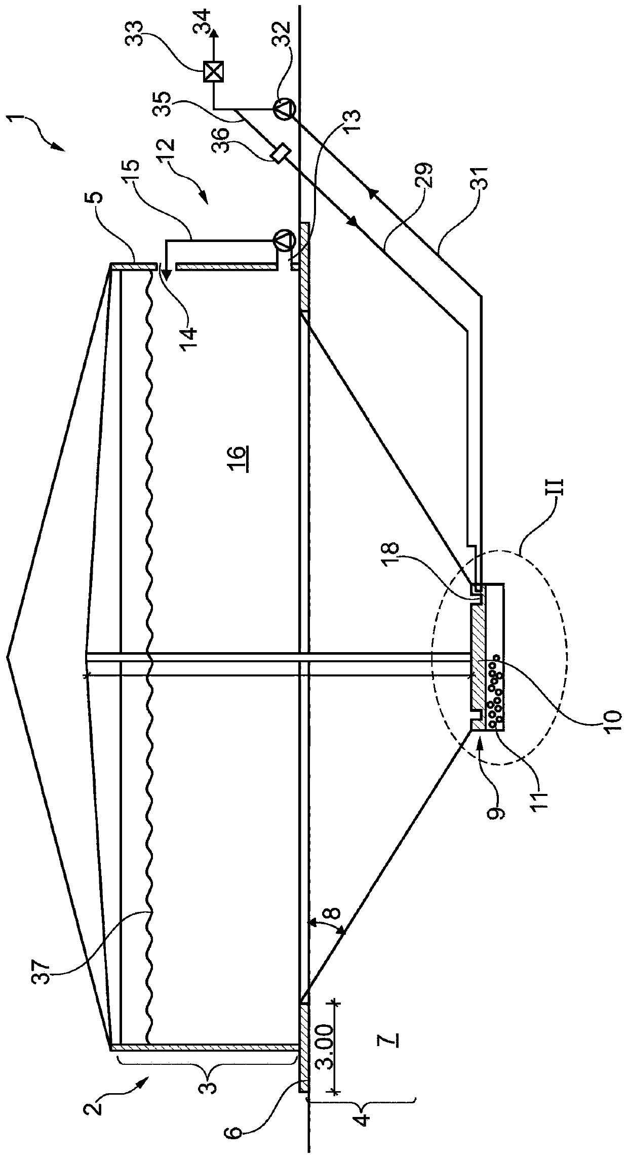
[0030] figure 1 A preferred embodiment of a biogas plant 1 according to the invention is shown in longitudinal section, which has an embodiment of the container 2 according to the invention. like infigure 1 As can be seen in , the container 2 has a cylindrical main section 3 to which a conical tapering section 4 is attached downwards. The cylindrical main section 3 has a wall 5 made of reinforced concrete. The wall 5 rests on an annular base 6 .

[0031] The conical tapering section 4 is located in the soil 7 in a lagoon-like manner. The tapering section 4 is made of PE-HD. The walls of the tapering section 4 form an angle 8 of 10°-45°, preferably 30°, with respect to the horizontal.

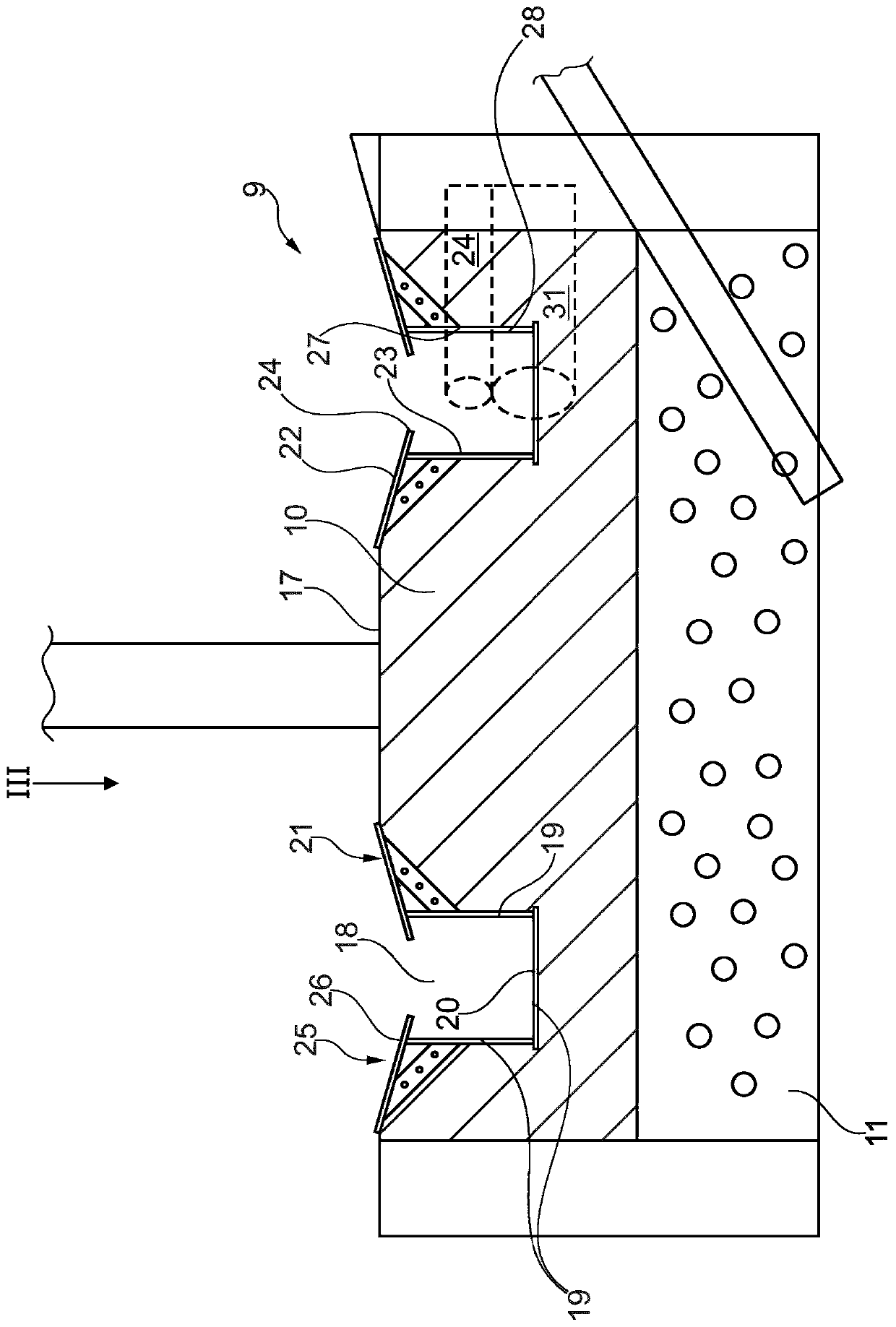
[0032] The tapering section 4 ends downwardly with a bottom section 9 . The bottom section 9 is substantially made of a floor 10 made of reinforced concrete. The floor 10 is installed on a gravel bed 11 in the soil 7 in the region of the floor 10 in order to possibly pump out groundwater. ...


PUM


Abstract

The invention relates to a container (2), particularly for producing biogas, comprising a preferably cylindrical main section (3) and a base section (9) that is positioned beneath said main section (3), as well as a biogas installation, which have a simple and cost-effective design that is easy to maintain, efficiently avoiding clogs and funneling at the container base, with low power consumption.To achieve this, it is suggested that the base section (9) comprises a circulation channel (18) that is closed into a ring.

Description

technical field [0001] The invention relates to a container, in particular for biogas production, having a preferably cylindrical main section and a bottom section arranged below the main section. [0002] The invention also relates to a biogas plant. Background technique [0003] Containers of the type mentioned at the outset are known in different designs and sizes, for example as components of biogas plants. The container is often designed as a steel tank or reinforced concrete tank and has a 400-6000m 3 volume. Organisms arranged to generate biogas in the form of a liquid slurry are filled into the container. The liquid mud is here in suspension, so that there are deposition problems. In conventional containers of biogas plants, the bottom is substantially planar. In practice, in the case of the previously known containers, therefore, problems often arise in biogas plants, namely, clogging and deposition of heavy substances at the bottom due to the sinking of heavy ...

Claims


Application Information

Patent Timeline
Patent Type & Authority Applications(China)
IPC IPC(8): C12M1/107C12M1/00
CPCC12M21/04C12M23/18Y02E50/30
Inventor C·奥伊斯特布罗克
Owner BIOENERGY CONCEPT GMBH
Why Eureka
Try Eureka