Cryoablation duct

A technology for ablation of catheters and tubes, applied in the direction of cooling surgical instruments, etc., can solve the problems of great difference in success rate, poor mapping effect, overheating of myocardial tissue, etc., and achieve the effect of increasing volume

Inactive Publication Date: 2019-05-07
SICHUAN JINJIANG ELECTRONICS SCI & TECH CO LTD
View PDF10 Cites 6 Cited by
  • Summary
  • Abstract
  • Description
  • Claims
  • Application Information

AI Technical Summary

Problems solved by technology

[0004] In order to achieve a deeper ablation depth, higher ablation energy will be used clinically, which will often cause local overheating of myocardial tissue and cause scab, thus affecting the effectiveness and safety of the operation. The saline cools down the ablation part, and a series of complications will occur due to the continuous delivery of saline to the patient during the operation
[0005] At the same time, the application of radiofrequency ablation in the treatment of atrial fibrillation faces many clinical problems: such as the risk of cardiac perforation, the temperature inconsistency between the surface layer of the myocardium and the interior, phrenic nerve injury, ablation carbonization/coagulum formation, a long learning curve for ablation of atrial fibrillation, and surgical Difficulty and technical requirements are very high, it is diff

Method used


Image

  • Cryoablation duct
  • Cryoablation duct
  • Cryoablation duct

Examples


Embodiment 1

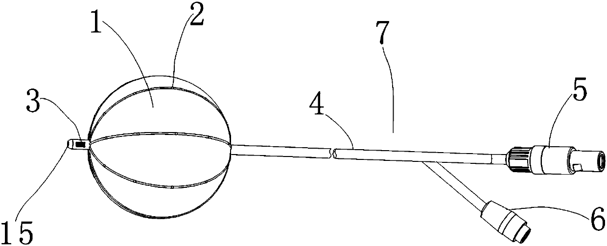
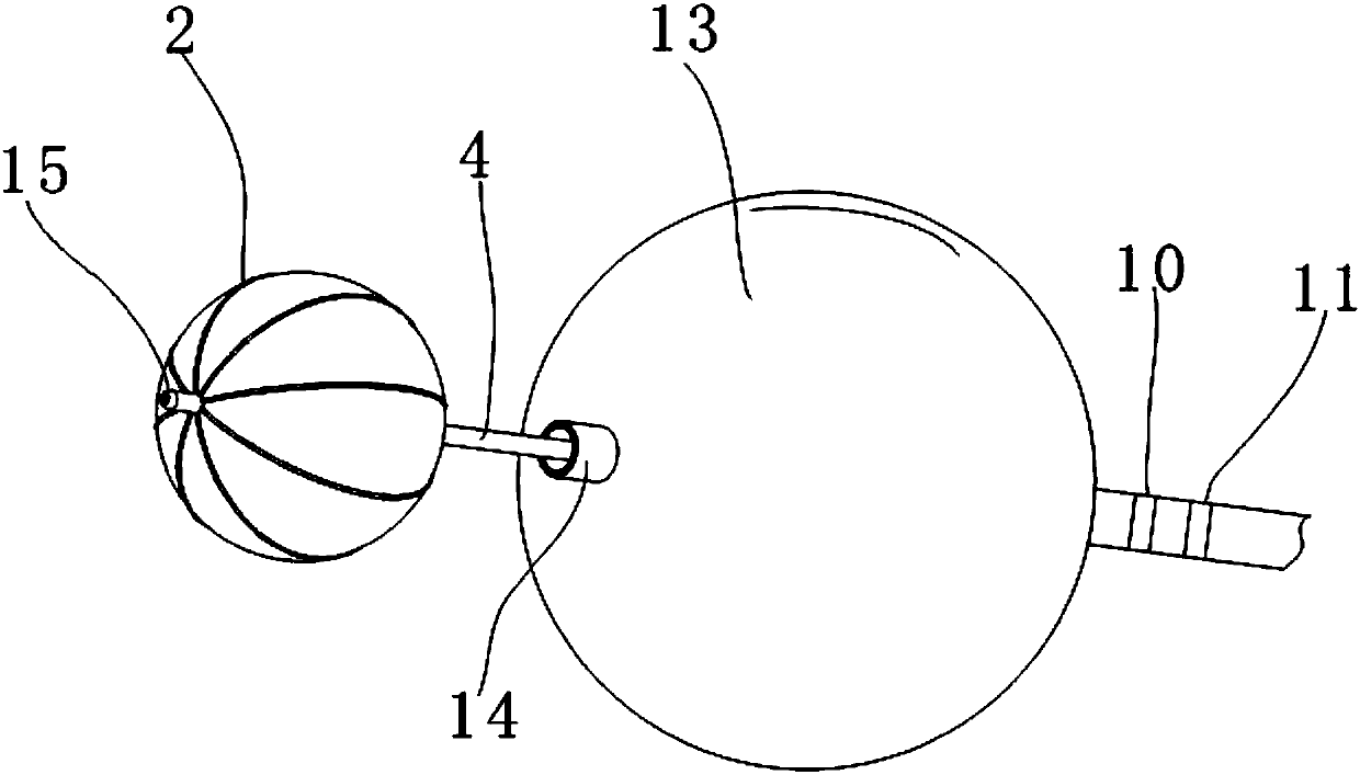
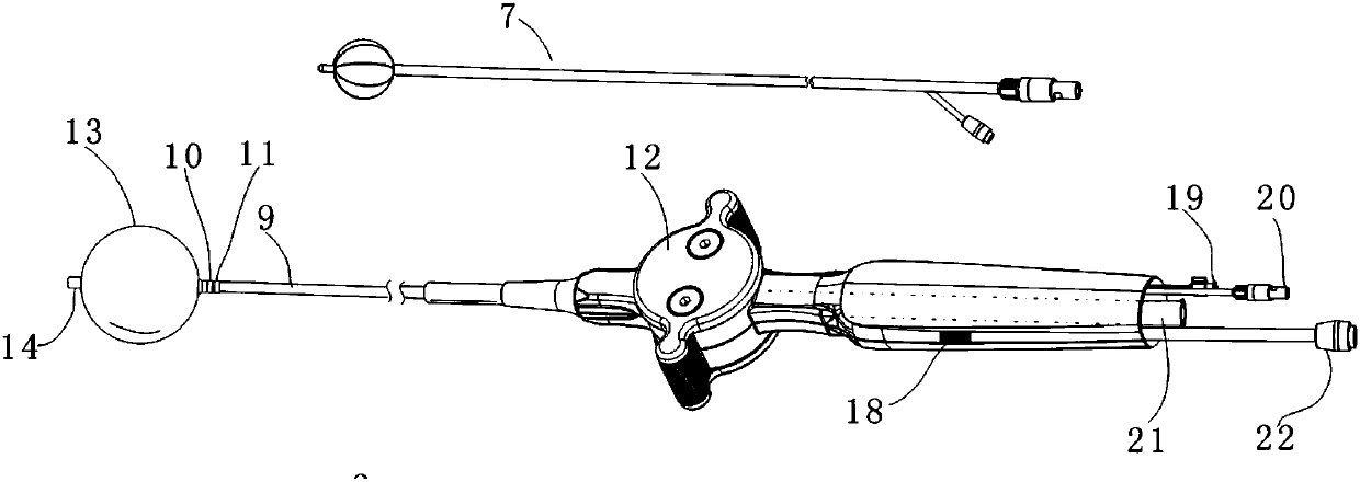
[0044] Such as Figure 1-4 , a cryoablation catheter comprising:

[0045] The distal tube body 9, the distal tube body 9 is the distal section of the entire tube body of the cryoablation catheter (the entire segment of the ablation catheter itself is the tube body, as opposed to, such as Figure 5 , the tube body at one end opposite to the distal tube body 9 is the proximal section of the catheter, which is the proximal tube body 16, and the material of the proximal tube body 16 is relatively harder than the distal tube body 9, Figure 5 is the figure of embodiment 2, which is only used to illustrate the proximal tube body 16);

[0046] An ablation balloon 13, the ablation balloon 13 is mounted on the end of the distal tube 9 for cryoablation;

[0047] A mapping balloon 1, the mapping balloon 1 has expansion and contraction functions and several mapping electrodes 2 are arranged on the surface of the mapping balloon 1, and the mapping balloon 1 is detachably arranged on the ...

Embodiment 2

[0062] Such as Figure 5 , 9 , in this embodiment, the difference from Embodiment 1 is that the several mapping electrodes 2 in the ablation catheter are circumferentially distributed on the surface of the mapping balloon 1 (when the mapping balloon 1 expands into a spherical , the mapping electrodes 2 appear to be arranged on the surface of the mapping balloon 1 in a circular array and arranged side by side in multiple circles), the electrodes can be arranged on the mapping ball in the form of metal, conductive polymer, conductive ink or printed circuit The surface of the balloon 1, or the electrodes can be adhesively bonded to the surface of the balloon, or through ion deposition or plasma deposition, after the electrodes are installed on the surface of the balloon 1 for mapping, other parts of the surface of the balloon 1 except for the electrodes can be measured Insulation, in this embodiment, the wires of the mapping electrode 2 are arranged along the supporting tube, an...


PUM


Abstract

The invention relates to the field of cryoablation, in particular to a cryoablation duct. The cryoablation duct comprises a far end duct body, a melt saccule and a mapping saccule, wherein the far endduct body is a far end segment of the entire duct body of a cryoablation duct; the melt saccule is mounted at the end of the far end duct body, and is used for cryoablation; the mapping saccule has functions of expanding and contraction, and a plurality of mapping electrodes are arranged on the surface of the mapping saccule; and the mapping saccule is detachably arranged in the far end tube bodyor the melt saccule. During operation, the mapping saccule extends out from the front end of the melt saccule. The invention aims to provide the cryoablation duct which can increase the mapping effect on mapping in frozen saccule melt of the heart.

Description

technical field [0001] The invention relates to the field of cryoablation, in particular to a cryoablation catheter. Background technique [0002] Radiofrequency ablation catheters or cryoablation catheters have been widely used clinically to treat arrhythmias in the atrium, such as atrial premature contraction, atrial flutter, bypass tachycardia, atrial fibrillation, and AV node reentry tachycardia , Ventricular arrhythmias in the ventricle, such as premature ventricular contractions, ventricular tachycardia, ventricular fibrillation, and heart diseases such as long-term QT ​​syndrome. [0003] For the treatment of most arrhythmias, radiofrequency ablation is safe and effective, but radiofrequency ablation still has limitations and disadvantages. Radiofrequency energy can destroy the structure and integrity of endothelium and tissue, and easily lead to the formation of thrombus and embolism. Excessive heat in radiofrequency can cause an increase in impedance and can cause...

Claims


Application Information

Patent Timeline
IPC IPC(8): A61B18/02
Inventor 邹波朱晓林李楚武
Owner SICHUAN JINJIANG ELECTRONICS SCI & TECH CO LTD
Why Eureka
Try Eureka