
Large-clamping-force machining device for hole in gate valve

A processing device and clamping force technology, which is applied in positioning devices, metal processing equipment, metal processing machinery parts, etc., can solve the problems of large processing volume, long processing cycle, and many processes, so as to improve work efficiency and workpiece processing accuracy High, high machine efficiency effect

Inactive Publication Date: 2019-05-07
十堰高明精密机械股份有限公司
View PDF0 Cites 0 Cited by
  • Summary
  • Abstract
  • Description
  • Claims
  • Application Information

AI Technical Summary

Problems solved by technology

The general processing method is to use a drilling machine to drill holes first, and then use a wire twisting machine for twisting processing. A single process corresponds to a single equipment processing product; this kind of processing method has many processes, long processing cycle and high processing cost.
[0003] In the field of mechanical processing of gate valve processing technology, there is an insurmountable problem of increasing the clamping force. The gate valve parts need to process two twisted wire holes, but this kind of valve has a large volume and a large amount of processing. The clamping force is also very large. To increase the clamping force, the pressure of the oil cylinder must be increased, or other methods. Therefore, there is an urgent need for a multi-functional machining equipment that can be used for multiple purposes, which is convenient for processing, improves processing efficiency, and solves the existing low production capacity. , backward processing technology and other defects

Method used


Image

  • Large-clamping-force machining device for hole in gate valve
  • Large-clamping-force machining device for hole in gate valve

Examples


Embodiment Construction

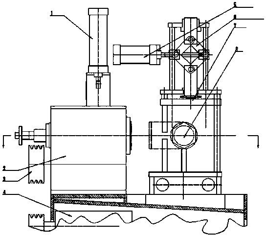
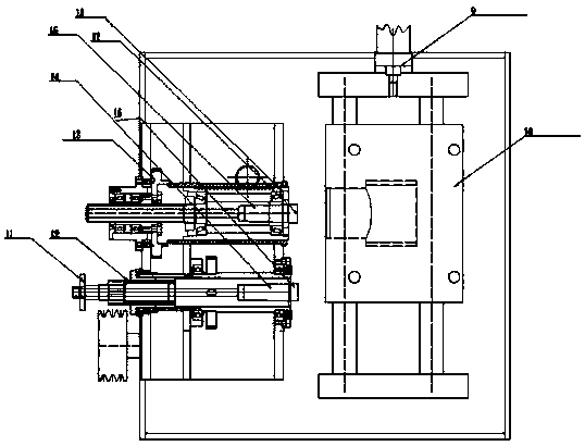
[0020] The reference signs shown in Fig. 1 and Fig. 2 are as follows: cylinder one 1, spindle box 2, pulley 3, motor 4, workpiece clamping cylinder 5, parallelogram booster mechanism 6, fixture 7, workpiece 8, cylinder two 9 , Two-station workpiece carriage 10, pawl 11, screw nut 12, gear 13, reaming spindle 14, reaming tap 15, milling cutter spindle 16, milling cutter 17, rack 18. Concrete implementation: a processing device with a large clamping force in the middle of a gate valve, mainly comprising a reaming wire spindle 14, a milling cutter spindle 16, a workpiece clamping cylinder 5, a parallelogram booster mechanism 6, 1 two-station workpiece carriage 10; the workpiece clamping cylinder 5 is in the middle of the machine tool; there is a parallelogram booster 6 on the right side of the workpiece clamping cylinder 5; the parallelogram booster can enlarge the cylinder The clamping force ranges from 2 tons to 5 tons, which solves the problem of increasing the pneumatic clamp...


PUM


Abstract

The invention discloses a large-clamping-force machining device for a hole in a gate valve. The device comprises a first air cylinder, a spindle box, a pulley, a motor, a workpiece clamping cylinder,a parallelogram force increasing mechanism, a clamp, a workpiece, a second air cylinder, a two-station workpiece dragging plate, a pawl, a screw nut, a gear, a hinge spindle, a hinge tap, a milling spindle, a milling cutter and a rack. The device is characterized in that the workpiece clamping cylinder is in the middle of a machine tool, the parallelogram force increasing mechanism is on the rightside of the workpiece clamping cylinder, the air cylinder pushes the parallelogram clamping device to clamp the workpiece to the clamp on the workpiece dragging plate, and the workpiece dragging plate has two stations. The workpiece is pneumatically clamped, the workpiece clamping device is large in clamping force and long in acting stroke, workpiece machining precision is high, and the machine tool efficiency is high.

Description

technical field [0001] The invention relates to the field of mechanical processing, in particular to a processing device with a large clamping force for the middle port of a gate valve. Background technique [0002] At present, in the field of mechanical processing, there are many parts that need to drill many holes, and then twist wires in these holes to form threaded holes. The general processing method is to use a drilling machine to drill holes first, and then use a wire twisting machine for twisting processing. A single process corresponds to a single equipment processing product; this kind of processing method has many processes, long processing cycle and high processing cost. [0003] In the field of mechanical processing of gate valve processing technology, there is an insurmountable problem of increasing the clamping force. The gate valve parts need to process two twisted wire holes, but this kind of valve has a large volume and a large amount of processing. The cl...

Claims


Application Information

Patent Timeline
IPC IPC(8): B23P23/02B23Q3/00
Inventor 岳琦
Owner 十堰高明精密机械股份有限公司
Learn More