
Energy dissipating anti-climbing device for railway locomotive head

A technology for railway locomotives and anti-climbers, applied in the direction of railway vehicle wheel guards/buffers, railway car body parts, transportation and packaging, etc., can solve the problems of difficult selection of material types, irreversible energy absorption behavior, limited energy absorption strength, etc. problem, to achieve the effect of protection safety, enhanced energy absorption effect, and convenient production

Active Publication Date: 2020-04-21
神州高铁轨道运维技术(北京)有限公司
View PDF6 Cites 0 Cited by
  • Summary
  • Abstract
  • Description
  • Claims
  • Application Information

AI Technical Summary

Problems solved by technology

[0005] Aiming at the deficiencies in the use of the existing anti-climbing device for railway locomotives proposed in the background technology, the present invention provides an energy-dissipating anti-climbing device for the head of a railway locomotive, which has multi-stage energy dissipation, and the energy-dissipating mechanism can be recycled, The advantage of strong adjustability of energy dissipation intensity solves the problems of limited energy absorption intensity due to the use of the deformation ability of metal itself to absorb energy, difficulty in selecting material types, and irreversible energy absorption behavior proposed in the above-mentioned background technology

Method used


Image

  • Energy dissipating anti-climbing device for railway locomotive head
  • Energy dissipating anti-climbing device for railway locomotive head
  • Energy dissipating anti-climbing device for railway locomotive head

Examples


Embodiment Construction

[0022] The following will clearly and completely describe the technical solutions in the embodiments of the present invention with reference to the accompanying drawings in the embodiments of the present invention. Obviously, the described embodiments are only some, not all, embodiments of the present invention. Based on the embodiments of the present invention, all other embodiments obtained by persons of ordinary skill in the art without making creative efforts belong to the protection scope of the present invention.

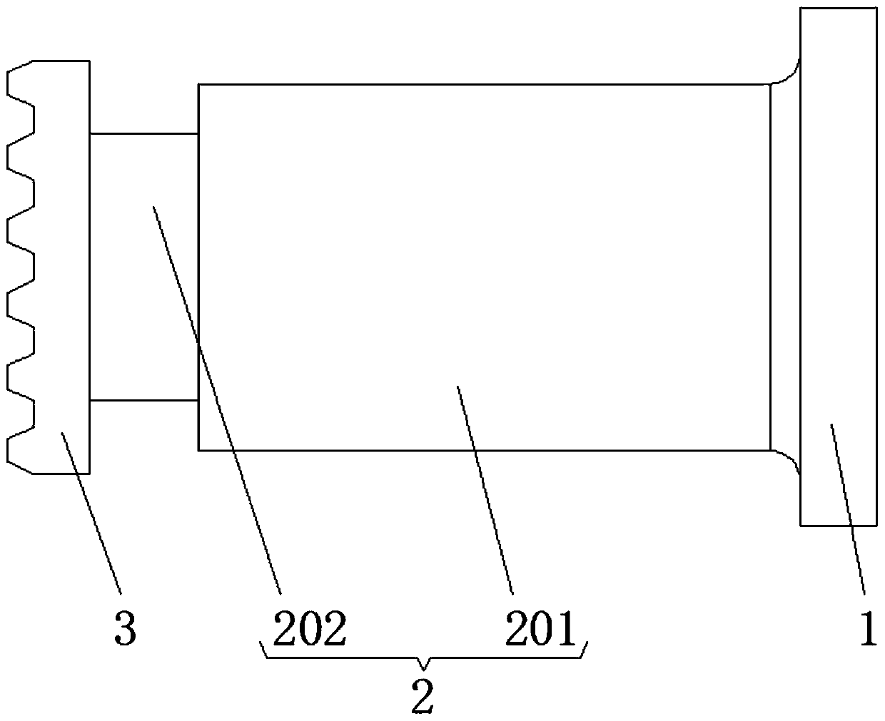
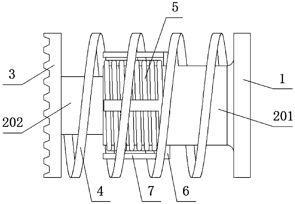
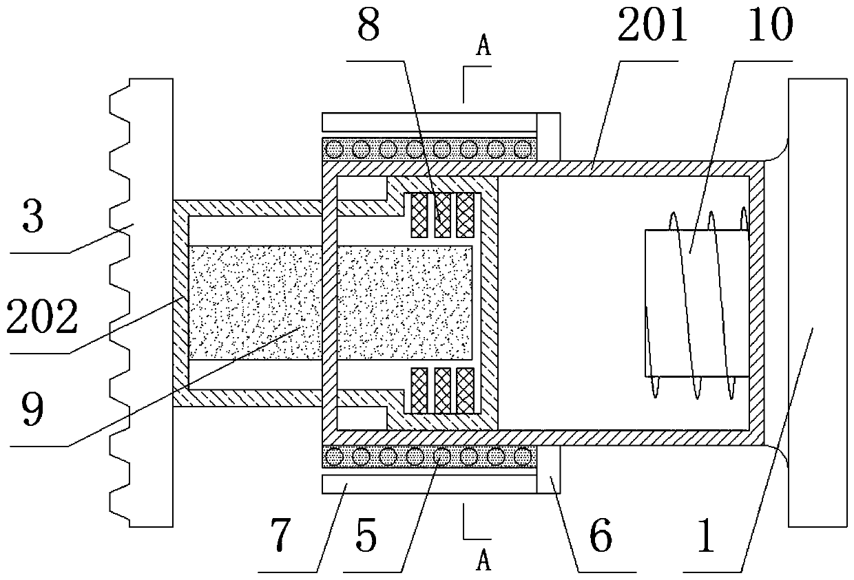
[0023] see Figure 1-5 , an energy dissipation anti-climbing device for a railway locomotive head, including a base 1, a guide mechanism 2 and a toothed plate 3, a guide mechanism 2 is provided between the base 1 and the toothed plate 3, and the guide mechanism 2 includes a guide cylinder I201 and a guide Tube II 202, one end of guide tube I 201 is fixedly connected with one side of base 1, guide tube I 201 is movably socketed with guide tube II 202, one end o...


PUM


Abstract

The invention relates to the technical field of rail traffic equipment and discloses an energy dissipation anti-creeper used for a railway locomotive. The energy dissipation anti-creeper used for therailway locomotive comprises a base, a guide mechanism and a toothed plate. The guide mechanism is arranged between the base and the toothed plate and comprises a guide barrel I and a guide barrel II.One end of the guide barrel I is fixedly connected with one side of the base. The guide barrel I and the guide barrel II are movably sleeved. An energy dissipation coil, permanent magnet iron platesand bar-shaped permanent magnets are arranged on the guide mechanism, when the locomotive is impacted and the toothed plate moves in an engaged mode, magnetic induction lines generated by the bar-shaped permanent magnets and the permanent magnet iron plates conduct cutting movement relative to the energy dissipation coil, current is generated in the energy dissipation coil, so that impact kineticenergy is converted into electric energy, the electric energy is then converted into heat energy through an energy dissipation resistor, impact energy is converted and absorbed, no destructive effectis generated in the energy absorption process, device components are manufactured conveniently, and reuse of energy absorption components can be guaranteed within the strength range of the guide barrel I and the guide barrel II.

Description

technical field [0001] The invention relates to the technical field of rail transit equipment, in particular to an energy dissipation and anti-climbing device for a railway locomotive head. Background technique [0002] During the running of the rail transit vehicle, in order to ensure the impact resistance performance, a series of energy-absorbing devices are set on the front of the vehicle. The three-level energy-absorbing protective barrier is composed of the coupler buffer device, the anti-climbing device and the deformable structure of the car body. Among them, the anti-climbing device is installed on the lower part of the rail transit vehicle to prevent the train from climbing when the two vehicles collide. Transformation absorption to ensure impact-resistant safety performance. [0003] Existing anti-climbing devices for trains such as figure 1 As shown, it includes a base (1), a guide mechanism (2) and a toothed plate (3). The base (1) is used to fix the correspond...

Claims


Application Information

Patent Timeline
Patent Type & Authority Patents(China)
IPC IPC(8): B61F19/04
Inventor 不公告发明人
Owner 神州高铁轨道运维技术(北京)有限公司
Learn More