Leakage petroleum recovery method and special equipment

A special equipment and oil technology, applied in the field of spilled oil recovery methods and special equipment, can solve the problems of low collection efficiency, increased cleaning costs, marine pollution, etc., and achieve the effects of easy secondary use, convenient operation, and improved purity

Active Publication Date: 2019-05-07
OCEAN RES CENT OF ZHOUSHAN ZHEJIANG UNIV
View PDF10 Cites 1 Cited by
  • Summary
  • Abstract
  • Description
  • Claims
  • Application Information

AI Technical Summary

Problems solved by technology

However, the use of chemical agents may cause new pollution to the ocean, and the large-scale use of chemical agents will greatly increase the cost of cleaning up pollution, so this method of cleaning up pollution is not widely used
Physical methods usually use fences to prevent the spread of oil, and then use oil suction machines to absorb oil, or put adsorbents on the sea surface to absorb oil. This method is not effective and inefficient. There are also large-scale mechanical collection methods. The cost of the method is too high, the energy consumption is too large, and the collection efficiency is low

Method used


Image

  • Leakage petroleum recovery method and special equipment
  • Leakage petroleum recovery method and special equipment
  • Leakage petroleum recovery method and special equipment

Examples


Embodiment 1

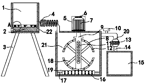
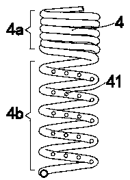
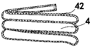
[0026] like Figure 1~4 As shown, a special equipment for recovery of leaked oil includes a static tank 1, a primary filter chamber 21, and a fine filter chamber 20. The bottom of the static tank 1 is supported by a support frame 3, and the static tank 1 is connected to the fine filter through a spiral oil outlet pipe 4. Chamber 21, fine filter chamber 21 inside is provided with a stirring device, the right side of fine filter chamber 21 is connected to oil collection pool 15 tops by bent pipe 14, and the vertical end of bent pipe 14 is provided with fine filter chamber 20, and bent pipe 14 The lateral end is provided with a control valve 10 . This device can recycle and filter oil, and the filtered oil can be used again. Oil filtration is divided into three steps, namely rapid oil-water separation, adsorption of magnetic impurities in oil and reduction of oil viscosity, and filtration of tiny particles in oil. , the filtration process is short, and the filtered oil has high ...

Embodiment 2

[0039] When the leaked oil recovery method and the special equipment of the present invention are actually used: the oil is first collected in the static pool 1, and the water sinks to the bottom of the pool through sedimentation, and the oil floats on the water surface to realize the stratification of the oil, and at the same time The large stones and debris contained in the oil will sink into the collection box 2 for centralized treatment. The high-frequency vibration device can accelerate the oil-water stratification in the static tank 1, and the vibration amplitude is small, and the dehydrated oil After entering the primary filter chamber 21, the stirring device stirs the oil, and the motor 7 is energized to drive the rotating shaft 9 to rotate rapidly, stirring the oil back and forth, effectively reducing the viscosity of the oil. The bottom of the primary filter chamber 21 is provided with a roller 19, which The magnetic block 16 on the surface of 19 can adsorb metal part...


PUM


Abstract

The invention provides a leakage petroleum recovery method and special equipment, and belongs to the technical field of petroleum leakage treatment. The special equipment comprises a standing tank, aninitial filtration chamber and a fine filtration chamber; the bottom of the standing tank is supported by a supporting frame; the standing tank is connected with the fine filtration chamber through aspiral oil outlet pipe; a stirring device is arranged in the fine filtration chamber; the right side of the fine filtration chamber is connected with the top of the oil collection tank through a bending pipe; the vertical end of the bending pipe is provided with the fine filtration chamber; and the transverse end of the bending pipe is provided with a control valve. According to the equipment, viscosity of petroleum can be reduced, the concentration of the petroleum is improved, the oil-water layering speed is high, and the filtered petroleum has high purity and can be reutilized.

Description

technical field [0001] The invention belongs to the technical field of oil leakage treatment, and in particular relates to a method for recovering oil leakage and special equipment. Background technique [0002] Petroleum is a viscous, dark brown liquid. There are oil reserves in parts of the upper crust. The main component is a mixture of various alkanes, naphthenes and aromatic hydrocarbons. As an important energy source, oil can be said to be the blood of modern economy. my country is a big oil consumer and the fifth largest oil producer in the world. As a basic industry, the petroleum industry requires a large number of technical personnel. The field of oil production is characterized by high technological content and strong technicality. However, oil pollution is also an important issue of concern to the world. Oil pollution refers to the pollution caused by oil leakage and discharge during the process of oil exploitation, transportation, loading and unloading, pro...

Claims


Application Information

Patent Timeline
Patent Type & Authority Applications(China)
IPC IPC(8): C02F9/02
Inventor 陈磊郑刚戴林伟黄海丽俞超超朱明栋
Owner OCEAN RES CENT OF ZHOUSHAN ZHEJIANG UNIV
Why Eureka
Try Eureka