Continuously variable transmission

A technology of continuously variable transmission and bucket wheel, which is applied in the direction of transmission device, gear transmission device, belt/chain/gear, etc., and can solve the problems of no increase in torque transmission, single transmission performance, and complex structural arrangement.

Active Publication Date: 2019-05-07
WEIHAI TUANZHONG TRANSMISSION CO LTD
View PDF5 Cites 2 Cited by
  • Summary
  • Abstract
  • Description
  • Claims
  • Application Information

AI Technical Summary

Problems solved by technology

[0009] The present invention is to solve the problem that the planetary gear sets at both ends of the continuously variable transmission limit the position of the end covers, and it is difficult to implement revolution control on the end covers on both sides of the cavity planetary frame; , the noise is large; the planetary wheel shaft and the bucket wheel planetary wheel shaft are not concentric, the planetary wheel shaft is outside the center of the bucket wheel planetary wheel shaft, and the structural arrangement is complicated; the input and output ends are fixed, resulting in a single transmission performance; there is no intermediate housing Inner wall structure scheme; in the case of other structures unchanged, there is no technical problem of increasing torque transmission alternatives, providing a three control ends formed by the outer shell, the first shaft and the second shaft, and gear meshing inside the outer shell Oil-rich lubrication, the shaft of the planetary wheel and the shaft of the planetary wheel of the bucket wheel are coaxial, and the inner wall of the housing is provided with a semicircular cavity corresponding to the bucket wheel. The bucket wheel is located in the semicircular cavity, and the ring gear replaces the sun gear to increase the torque transmission. Multifunctional and continuously variable transmissions for different working conditions

Method used


Image

  • Continuously variable transmission
  • Continuously variable transmission
  • Continuously variable transmission

Examples


Embodiment 1

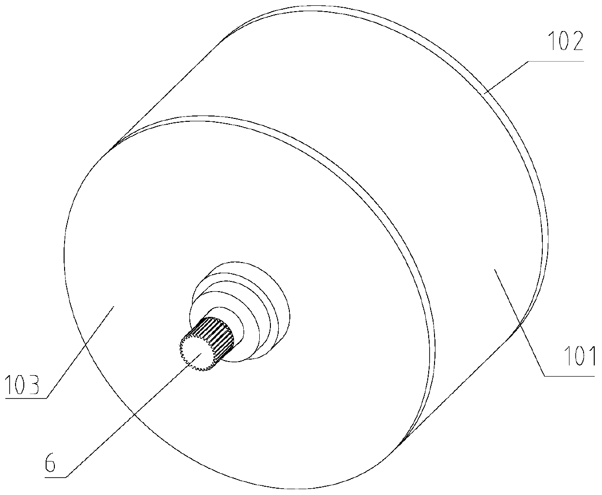
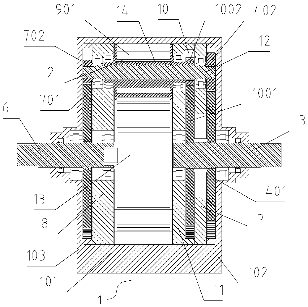
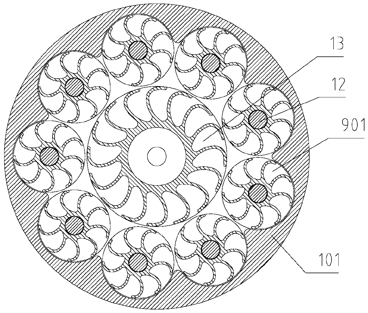
[0036] Such as Figure 1-Figure 6 As shown, it is an embodiment of a continuously variable transmission of the present invention, which is provided with an outer casing 1, an intermediate casing 101 is arranged in the middle of the outer casing 1, and a first end cover 102 and a second end cover 102 are respectively arranged on both sides of the intermediate casing 101. The end cover 103, the inside of the middle housing 101 is a cavity structure, the cavity inside the middle housing 101 and the inner side of the first end cover 102 and the second end cover 103 form an inner cavity 2; the first end cover 102 runs through the middle There is a first shaft 3, the first shaft 3 is rotatably connected with the first end cover 102, the first sun gear 401 is fixed on the first shaft 3, the first sun gear 401 is located inside the first end cover 102, the first The sun gear 401 is adjacently provided with a first support frame 5, the first shaft 3 passes through the first support fra...

Embodiment 2

[0046] Figure 7-12 Shown is another embodiment of a continuously variable transmission of the present invention, an outer casing 1 is provided, an intermediate casing 101 is arranged in the middle of the outer casing 1, and a first end cover 102 and a first end cover 102 are respectively arranged on both sides of the intermediate casing 101 The second end cover 103, the inside of the intermediate housing 101 is a cavity structure, and the cavity inside the intermediate housing 101 forms an inner cavity 2 with the inner side of the first end cover 102 and the second end cover 103; the first A first shaft 3 runs through the middle of the end cover 102, and the first shaft 3 is rotatably connected with the first end cover 102. A first ring gear 401A is fixed on the first shaft 3, and the first ring gear 401A is located at the first end. Inside the cover 102, the first ring gear 401A is adjacent to a first support frame 5, the first shaft 3 passes through the first support frame ...

Embodiment 3

[0050] refer to figure 2 and image 3 , a continuously variable transmission, which is provided with an outer casing 1, an intermediate casing 101 is arranged in the middle of the outer casing 1, and a first end cover 102 and a second end cover 103 are respectively arranged on both sides of the intermediate casing 101, and the middle The inside of the housing 101 is a cavity structure, and the cavity inside the intermediate housing 101 and the inner side of the first end cover 102 and the second end cover 103 form an inner cavity 2; the first end cover 102 is provided with a first Shaft 3, the first shaft 3 is rotatably connected with the first end cover 102, the first sun gear 401 is fixed on the first shaft 3, the first sun gear 401 is located inside the first end cover 102, and the first sun gear 401 is adjacent A first support frame 5 is provided, the first shaft 3 passes through the first support frame 5, and the first shaft 3 is rotatably connected with the first suppo...


PUM


Abstract

The invention provides a continuously variable transmission. The continuously variable transmission is provided with an outer shell, an inner cavity, a first planet gear set and a second planet gear set; a bucket wheel sun wheel is fixedly arranged on a first shaft penetrating through a first support frame; the bucket wheel sun wheel is located on the inner side of the first support frame; a bucket wheel planet wheel is arranged on the outer circumference of the bucket wheel sun wheel; the bucket wheel planet wheel is engaged with the bucket wheel sun wheel; the bucket wheel planet wheel and the bucket wheel sun wheel form a bucket wheel planet gear set; a third support frame is arranged adjacent to the bucket wheel sun wheel; a bucket wheel planet wheel shaft is fixed in the middle of thebucket wheel planet wheel; the interior of the bucket wheel planet wheel shaft is of a hollow structure; the planet wheel shaft penetrates through the first support frame, the hollow bucket wheel planet wheel shaft and a second support frame; and the planet wheel shaft is rotationally connected with the first support frame and the second support frame. The continuously variable transmission withthree control ends formed by the outer shell, the first shaft and a second shaft is provided and can be widely applied to the field of transmission.

Description

technical field [0001] The invention relates to a mechanical transmission device, in particular to a continuously variable transmission. Background technique [0002] The existing domestic patent authorization number is a continuously variable transmission with ZL2017205424112, and its technical solution is: a continuously variable transmission, including an input planetary gear set and an output planetary gear set, an input planetary gear set and an output planetary gear set There is a cavity planetary carrier between them. The cavity planetary frame includes a cavity input end cover and a cavity output end cover. A bucket wheel cavity shell is fixed between the cavity input end cover and the cavity output end cover. The inner side of the planetary gear set is connected to the input end cover of the cavity, and the inner side of the planetary gear set at the output end is connected to the output end cover of the cavity. There is a planetary gear connecting shaft in the mid...

Claims


Application Information

Patent Timeline
Patent Type & Authority Applications(China)
IPC IPC(8): F16H3/76F16H57/031
CPCF16H47/12F16H57/021F16H57/031F16H2057/0216
Inventor 唐永峰唐玉凝
Owner WEIHAI TUANZHONG TRANSMISSION CO LTD
Why Eureka
Try Eureka