
Large temperature difference central heating system using electric compression type heat pump

A compression heat pump and central heating technology, applied in hot water central heating systems, heating systems, and central heating, can solve problems such as changes in steam turbine operating conditions, complex construction levels, and changes in condenser vacuum, etc. Increase the heating capacity, ensure the heating effect, and reduce the difficulty of transformation

Pending Publication Date: 2019-05-07
XIAN HUAXIN NEW ENERGY CO LTD
View PDF3 Cites 3 Cited by
  • Summary
  • Abstract
  • Description
  • Claims
  • Application Information

AI Technical Summary

Problems solved by technology

Since the return water temperature of the heating network is related to the water supply temperature, weather conditions, user needs, etc., only controlling the flow of the return water entering the condenser through the bypass valve will change the vacuum degree of the condenser, resulting in the failure of the steam turbine to operate. situation changed
[0014] 3. When the system uses the steam absorption heat pump to recover the heat of the circulating cooling water, steam is needed as the driving heat source. The construction of the steam pipeline needs to consider many issues such as space and heat preservation, and the construction level is complicated.
[0017] 1. The heating process of the power plant side adopts the steam absorption lithium bromide unit, and the steam turbine extraction is used as the driving heat source, which is not suitable for the "Three North" regions with "more electricity and less heat"
[0018] 2. At present, most of the heat supply uses terminal systems such as ground radiation heat, fan coils, and radiators. The required inlet and return water temperature is higher than 30°C. Through the heat exchange coil in the thermal cooling tower, it is impossible to connect the primary heating pipe network Return water temperature drops to 30°C
In order to reduce the return water temperature of the primary pipe network to 30°C, the air can only be used to take away part of the heat in the thermal cooling tower, resulting in a waste of energy
[0019] 3. When the system uses the steam absorption heat pump to recover the heat of the circulating cooling water, steam is needed as the driving heat source. The construction of the steam pipeline needs to consider many issues such as space and heat preservation, and the construction level is complicated.
[0021] 1. The heating process of the power plant side adopts the steam absorption lithium bromide unit, and the steam turbine extraction is used as the driving heat source, which is not suitable for the "Three North" regions with "more electricity and less heat"
[0022] 2. The return water temperature of the heating network passing through urban users is 60°C. If there is no agricultural greenhouse to absorb heat near the urban heating pipe network, the return water temperature of the heating network cannot be reduced to 30°C
[0023] 3. When the system uses the steam absorption heat pump to recover the heat of the circulating cooling water, steam is needed as the driving heat source. The construction of the steam pipeline needs to consider many issues such as space and heat preservation, and the construction level is complicated.

Method used


Image

  • Large temperature difference central heating system using electric compression type heat pump

Examples


Embodiment Construction

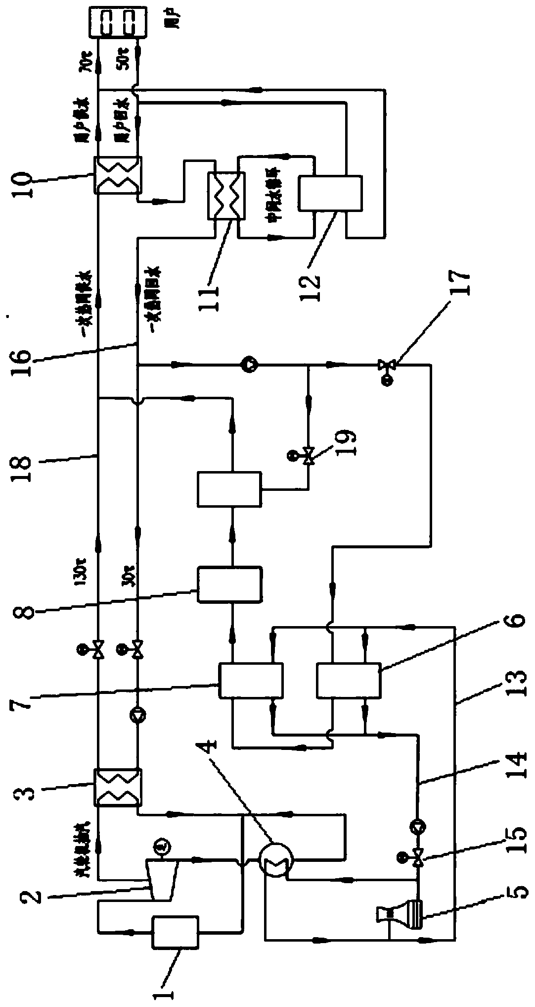
[0042] The structural principle and working principle of the present invention will be further described in detail below in conjunction with the accompanying drawings.

[0043] see figure 1 , the large temperature difference centralized heating system utilizing the electric compression heat pump provided by the present invention includes a steam turbine 2 connected to the boiler 1, and part of the medium-temperature and medium-pressure steam extracted by the steam turbine 2 is connected to the steam-water heat exchanger 3 through pipelines, The primary heating network supply water formed by heating the return water of the primary heating network through the steam-water heat exchanger 3 is then heat-exchanged by the first water-water heat exchanger 10 and then supplied to end users.

[0044] After the steam-water heat exchanger 3 releases heat, the condensed water is connected to the boiler 1 through pipes. The exhaust gas from the last stage of the steam turbine 2 is connecte...


PUM


Abstract

The invention discloses a large temperature difference central heating system using an electric compression type heat pump. The large temperature difference central heating system comprises a condenser and a cooling tower which form a circulation loop, the cooling tower is connected to a medium temperature heat pump and a high temperature heat pump through a circulating cooling water return waterpipeline, a part of circulating cooling water from the condenser enters the cooling tower, and a part of the circulating cooling water enters the medium temperature heat pump and the high temperatureheat pump through the circulating cooling water return water pipeline; the circulating cooling water discharged out from the medium temperature heat pump and the high temperature heat pump passes through a circulating cooling water supply pipe and the condenser; and primary heat network return water is connected to the medium temperature heat pump through a pipeline and a second valve installed onthe pipeline, primary heat network return water heated by the medium temperature heat pump sequentially passes through a first high temperature heat pump, an electrode heating device and a heat storage device to communicate with a primary heat network water supply pipe. On the basis of an existing turbine steam extraction heating system, a thermal power plant side electric heating system is connected in parallel, and under the condition that the thermal power plant running working condition is not changed, the heating capacity of a pipe network is increased.

Description

technical field [0001] The invention relates to a heat supply system, in particular to a centralized heat supply system with large temperature difference using an electric compression heat pump. Background technique [0002] At present, the Northeast, North China, and Northwest regions (hereinafter referred to as the "Three Norths" region) are the regions with the most abundant wind energy resources in my country, and are also the regions with the most serious "abandoned wind" phenomenon. In 2015, the abandoned wind power was as high as 33.9 billion kWh, " Wind abandonment has become the main bottleneck restricting the healthy development of wind power in my country. Developing an electricity market that can replace fossil energy in areas rich in wind energy resources is the key to solving local consumption. [0003] Due to the continuous development of the cities in the "Three Norths" region, the central heating area is gradually increasing. It is an urgent problem to incre...

Claims


Application Information

Patent Timeline
IPC IPC(8): F24D3/10F24D3/18F24D11/00
Inventor 史晓云雷琰
Owner XIAN HUAXIN NEW ENERGY CO LTD
Learn More