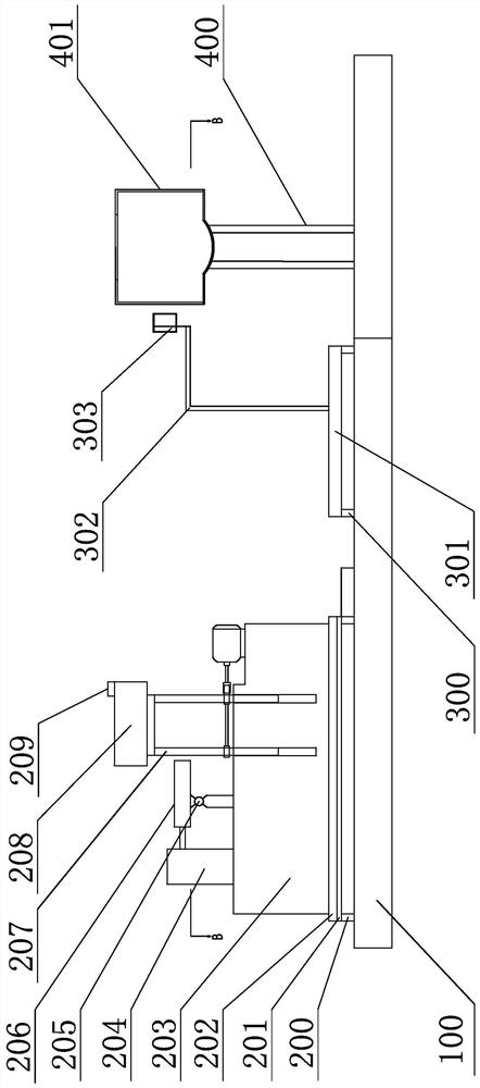
Auricular point automatic positioning device, positioning system and positioning method for assisting ear point pressing seeds
An automatic positioning and ear technology, applied in the direction of equipment for compressing reflection points, equipment for determining reflection points, image analysis, etc., can solve the problems of ear image acquisition and low accuracy of acupoint positioning, so as to improve accuracy and avoid Decreased positioning accuracy to ensure the effect of treatment
- Summary
- Abstract
- Description
- Claims
- Application Information
AI Technical Summary
Problems solved by technology
Method used
Image
Examples
specific Embodiment approach 1
[0052] Specific implementation mode one: combine Figure 1 to Figure 3 To describe this embodiment,
[0053] The current automatic positioning device for ear acupoints is based on collecting ear images on one side of the head, that is, collecting images in a direction perpendicular to the user's realization. Since the user's auricle does not grow perpendicular to the head, it is at a certain angle to the head, and the angle of each person's auricle is also different, that is, the growth posture of each person's auricle is different. The pinna will be closer to the head; some people's pinna will be raised and slightly farther away from the head, through Figure 5 and Figure 6 It can be seen that the area of the ear image obtained by directly collecting images on one side is relatively small (equivalent to a relatively small projected area), and the area of each part of the auricle will also be small, which not only causes a certain impact on the fitting. Difficulties, bu...
specific Embodiment approach 2
[0061] Specific implementation mode two: combination Figure 4 To describe this embodiment,
[0062] In the ear acupoint automatic positioning device for auxiliary auricular point pressing seeds in this embodiment, the rotating baffle 303 is arranged on the baffle bracket 302 through the rotating shaft 331, and the rotating shaft deviates from the rotating baffle and is symmetrically drawn, that is, the rotating shaft is offset set to form an asymmetric baffle surface, that is, the small baffle surface end 332 and the large baffle surface end 333.
[0063] This structure ensures that when the rotating baffle is close to the auricle from one side, the surface end of the large baffle is in contact with the auricle first, and the rotating baffle continues to move toward the auricle. Partial contact will generate a force opposite to the direction of motion of the rotating baffle, and this force will generate a moment around the offset rotating shaft, making the rotating baffle ro...
specific Embodiment approach 3
[0065] Specific implementation mode three: combination Figure 7 to Figure 8 To describe this embodiment,
[0066] In the ear point automatic positioning device for assisting ear point pressing seeds in this embodiment, the bottom of the head fixing frame 401 is provided with a jaw fixing part 412 arched downward, and the upper side of the head fixing frame 401 is provided with a There is a forehead fixing part 411 that is horizontally arched in the same direction as the forehead.
[0067] If only the support of the jaw may cause the head to swing back and forth with the support of the jaw as the fulcrum, the angle and position of the ear image collection are uncertain, even when the ear image is collected The ear image is blurred or the position of the positioning is wrong due to the shaking of the head. With the head fixing frame of this embodiment, the fixing part of the jaw is downward, and the fixing part of the forehead is horizontally forward, so that the head can be ...
PUM
 Abstract
Description
Claims
Application Information
 - R&D
- Intellectual Property
- Life Sciences
- Materials
- Tech Scout
- Unparalleled Data Quality
- Higher Quality Content
- 60% Fewer Hallucinations
Browse by: Latest US Patents, China's latest patents, Technical Efficacy Thesaurus, Application Domain, Technology Topic, Popular Technical Reports.
© 2025 PatSnap. All rights reserved.Legal|Privacy policy|Modern Slavery Act Transparency Statement|Sitemap|About US| Contact US: help@patsnap.com


