Agricultural machine transverse transmission rod limiting support welding device and welding positioning device thereof

A technology for welding positioning and limit brackets, which is applied to welding equipment, welding equipment, auxiliary devices, etc., can solve the problems of positioning accuracy errors, low processing efficiency, and large production input manpower, etc., to achieve stable positioning and good positioning effects Effect

Active Publication Date: 2019-05-10
HENAN UNIV OF SCI & TECH
View PDF9 Cites 0 Cited by
  • Summary
  • Abstract
  • Description
  • Claims
  • Application Information

AI Technical Summary

Problems solved by technology

[0003] The shaft part and the arc part of the limit bracket are connected by welding. When the limit bracket is mass-produced in the factory, the welding between the shaft part and the arc part needs to be precisely positioned to achieve accurate welding of the two. Specifically, In the prior art, when welding the shaft part and the arc part, the shaft part and the arc part need to be positioned first, and then the welding is performed manually after the positioning is completed. After the welding is completed, the limit bracket is removed, and then the lowe...

Method used


Image

  • Agricultural machine transverse transmission rod limiting support welding device and welding positioning device thereof
  • Agricultural machine transverse transmission rod limiting support welding device and welding positioning device thereof

Examples


Embodiment Construction

[0027] Embodiments of the present invention will be further described below in conjunction with the accompanying drawings.

[0028] A specific embodiment of the welding device for the limit bracket of the horizontal transmission rod of the agricultural machinery of the present invention:

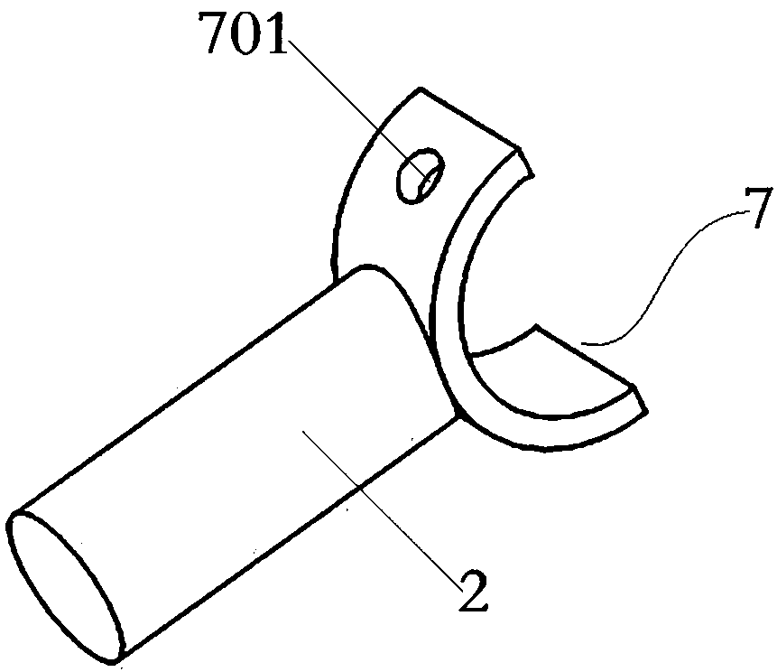
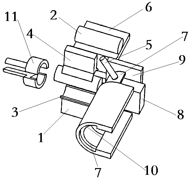
[0029] The welding device for the limit bracket of the horizontal transmission rod of agricultural machinery includes a welding positioning device and a welding mechanism for welding the arc and shaft parts that are pressed together. The welding mechanism is a resistance welding machine. The resistance welding machine includes a power supply and is connected to the power supply. The first electrode terminal and the second electrode terminal (the specific structure and use form of the resistance welding machine are consistent with the structure and use of the resistance welding machine in the prior art, so only the connection position of the electrodes is given in the figure, the technical fie...


PUM


Abstract

The invention relates to an agricultural machine transverse transmission rod limiting support welding device and a welding positioning device thereof. The agricultural machine transverse transmissionrod limiting support welding positioning device comprises a machine frame, a shaft part positioning seat is arranged on the machine frame, and a shaft part positioning structure is arranged on the shaft part positioning seat; an arc part positioning seat is further arranged on the machine frame, and a positioning piece and a stop positioning structure are arranged on the arc part positioning seat;and the welding positioning device further comprises a pressure contact driving mechanism, a shaft part feeding mechanism and an arc part feeding mechanism, wherein the shaft part feeding mechanism and the arc part feeding mechanism are arranged on the machine frame, and an in-place controller is arranged on the arc part feeding mechanism. The shaft part and the arc part are accurately conveyed to the shaft part positioning seat and the arc part positioning seat correspondingly, the shaft part positioning structure is used for positioning the shaft part, a positioning pin and the positioningpiece are used for positioning the arc part, the pressure contact driving mechanism applies acting force on the shaft part and/or the arc part to enable the shaft part and the arc part to be close toeach other, and finally, the arc part and the shaft part are welded through a welding mechanism. In this way, the positioning precision of the shaft part and the arc part is greatly improved, and thewelding efficiency is also improved.

Description

technical field [0001] The invention relates to a welding device for a limit bracket of an agricultural machinery transverse transmission rod and a welding positioning device thereof. Background technique [0002] Agricultural machinery cross drive rods are used in the power transmission of modern agricultural machinery, most commonly found in tractors and agricultural implements, or used in the power transmission between the power output and input ends of the agricultural machinery itself, so that the agricultural machinery can achieve a normal working relationship , and the limit bracket applied to the horizontal transmission rod of agricultural machinery plays an important role in the installation limit of the horizontal transmission rod of agricultural machinery. Such as figure 1 As shown, the limit bracket of the horizontal transmission rod of agricultural machinery mainly includes the shaft part 2 and the arc part 7 arranged at the end of the shaft part 2. The arc par...

Claims


Application Information

Patent Timeline
IPC IPC(8): B23K11/36B23K37/04B23K11/00
CPCB23K11/36B23K11/362B23K37/0443B23K11/002
Inventor 石红信邱然锋赵培峰马恒波任柯旭张肖飞
Owner HENAN UNIV OF SCI & TECH
Why Eureka
Try Eureka