Steel plate surface leveling and deburring device

A technology for surface flattening and steel plate, applied in the direction of grinding drive device, grinding machine, grinding machine parts, etc., can solve the problems of poor adjustability, low grinding and leveling efficiency, etc., to achieve complete deburring, excellent deburring effect, and sufficient grinding. Effect

Inactive Publication Date: 2019-05-10
卢彭
View PDF7 Cites 5 Cited by
  • Summary
  • Abstract
  • Description
  • Claims
  • Application Information

AI Technical Summary

Problems solved by technology

[0003] During the production and processing of steel plates, due to the processing technology, a large number of burrs will be generated on the surface of the steel plate. In order to ensure the processing quality of the steel plate, these burrs need to be removed by grinding to achieve a smooth surface of the steel plate. The adjustment of the device is poor, and the efficiency of grinding and smoothing is low, which cannot meet the actual use requirements. Therefore, a steel plate surface smoothing and deburring device is now provided to solve the above technical problems

Method used


Image

  • Steel plate surface leveling and deburring device
  • Steel plate surface leveling and deburring device
  • Steel plate surface leveling and deburring device

Examples


Embodiment 1

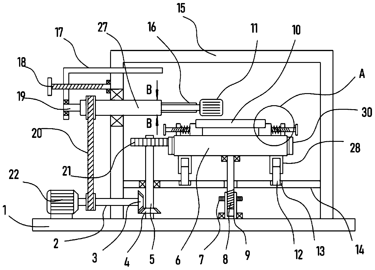
[0021] see Figure 1-3 , a steel plate surface leveling and deburring device, comprising a support base plate 1, a support frame 15 is fixed on the support base plate 1, a horizontal plate 14 is horizontally fixed on the support frame 15, and a turntable 6 is arranged on the horizontal plate 14 in a rotating manner. A clamping mechanism for clamping the steel plate 10 is installed.

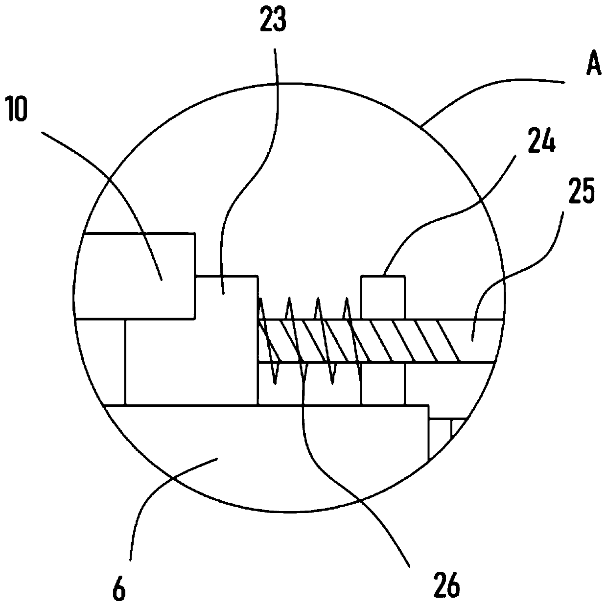
[0022] Before performing the deburring operation on the surface of the steel plate, the steel plate 10 is clamped and fixed on the turntable 6 by a clamping mechanism. A fixed plate 24 is fixed on the fixed plate 24, and the threaded connection on the fixed plate 24 is provided with a locking screw 25 that abuts against the block 23. Limiting spring 26.

[0023] The specific operation of the clamping process is as follows: place the steel plate 10 on the block 23, and push the block 23 to move toward each other by rotating the locking screw 25 to clamp and fix the steel plate 10 from both sides,...

Embodiment 2

[0028] On the basis of Embodiment 1, the drive motor 22 that is connected to the output shaft and the transmission sleeve 27 through the pulley mechanism 20 is provided on the support base plate 1, and the output shaft of the drive motor 22 is coaxially fixed with the driving bevel gear 3, and the driven shaft 5 is sleeved with a driven bevel gear 4 meshing with the driving bevel gear 3 .

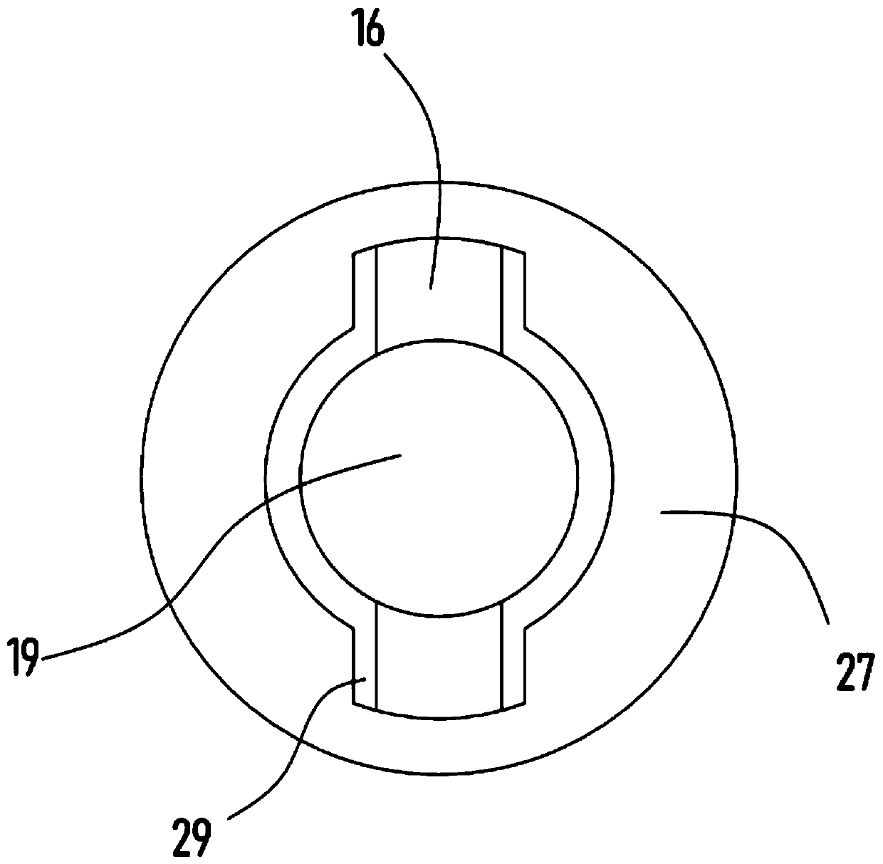
[0029] The driving motor 22 is used as the only power output of the device, and the driving motor 22 drives the driving shaft 2 to rotate, and the driving shaft 2 drives the transmission sleeve 27 to rotate through the pulley mechanism 20, and then realizes that the transmission column 19 drives the grinding head 11 to rotate, and at the same time, the driving The shaft 2 drives the driving bevel gear 3 to rotate, and the driving bevel gear 3 drives the driven shaft 5 to rotate through the driven bevel gear 4 meshing with it, and then realizes the meshing transmission between the driving gea...


PUM


Abstract

The invention discloses a steel plate surface leveling and deburring device, and relates to the technical field of steel plate processing. The steel plate surface leveling and deburring device comprises a support bottom plate, a support frame is fixed on the support bottom plate, a horizontal plate is fixed horizontally on the support frame, a rotary disc is rotationally arranged on the horizontalplate, a clamping mechanism for clamping a steel plate is mounted on the rotary disc, and a driven shaft which is vertically arranged is pivoted to the horizontal plate. By means of the steel plate surface leveling and deburring device, a polishing head rotates to achieve polishing on the surface of the steel plate on the rotary disc, the rotary disc can drive the steel plate to rotate, the surface of the steel plate is more fully polished, and the deburring effect is more excellent. The polishing head adjusts the lateral position by adjusting the rotation of a screw rod, so that the specificposition of the steel plate is polished, and the deburring process is more targeted; and by rotating a rotating sleeve, a threaded sleeve can be driven to rotate, height lifting of the steel plate isrealized, adjustment of the polishing strength of the polishing head on the surface of the steel plate is realized, adjustment according to actual needs is facilitated, and deburring is more thorough.

Description

technical field [0001] The invention relates to the technical field of steel plate processing, in particular to a steel plate surface smoothing and deburring device. Background technique [0002] The steel plate is a flat steel material casted with molten steel and pressed after cooling. It is flat and rectangular, and can be directly rolled or cut from a wide steel strip. The steel plate is divided according to the thickness. The thickness of the thick steel plate is 4-60 mm, and the thickness of the extra-thick steel plate is 60-115 mm; the steel plate is divided into hot rolling and cold rolling according to rolling, and the width of the thin plate is 500-500 mm; Sheets are classified by steel type, including ordinary steel, high-quality steel, alloy steel, spring steel, stainless steel, tool steel, heat-resistant steel, bearing steel, silicon steel, and industrial pure iron sheets, etc.; by professional use, there are plates for oil drums, Enamel plates, bulletproof pla...

Claims


Application Information

Patent Timeline
IPC IPC(8): B24B9/04B24B41/00B24B41/06B24B47/12B24B47/22
Inventor 卢彭
Owner 卢彭
Why Eureka
Try Eureka