Wood cutting device for forestry engineering

A cutting device and wood technology, applied in the direction of feeding device, clamping device, wood processing equipment, etc., can solve the problems of limited application range, user injury, wood deviation, etc., to solve the problem of relatively limited application range and avoid scrapping , smooth cutting effect

Active Publication Date: 2019-05-10
陈芬芬
View PDF5 Cites 20 Cited by
  • Summary
  • Abstract
  • Description
  • Claims
  • Application Information

AI Technical Summary

Problems solved by technology

At present, when the wood cutters on the market are in use, the user needs to press the wood with his hands to fix the wood when cutting. When the technology is used, the wood is cut by the saw blade, but when there is no mechanical fixation, the wood is easy to shift, thereby causing the scrap of the wood, which seriously wastes the wood resources, and the limiting device in the prior art does not Can not adapt to different sizes of wood, the scope of application is relatively limited

Method used


Image

  • Wood cutting device for forestry engineering
  • Wood cutting device for forestry engineering
  • Wood cutting device for forestry engineering

Examples


specific Embodiment approach 1

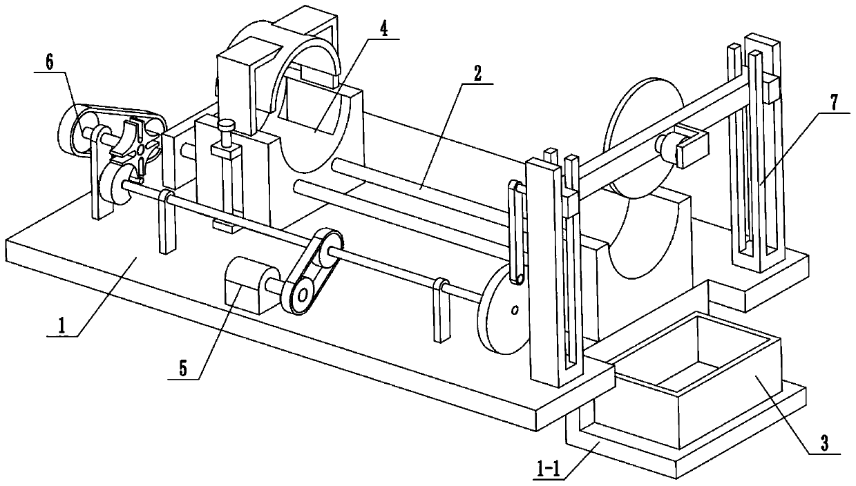
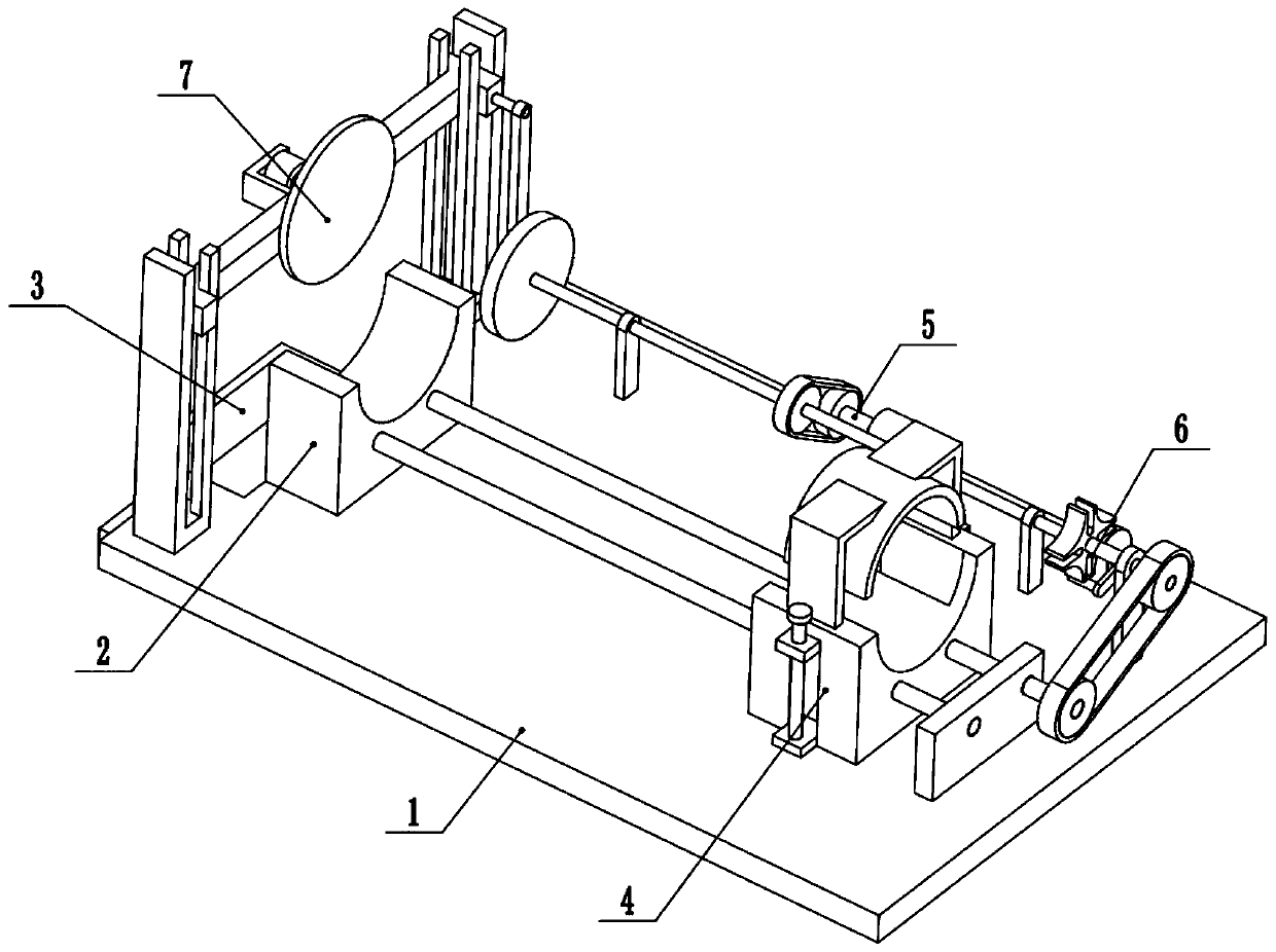
[0030] Combine below Figure 1-11Description of this embodiment, a wood cutting device for forestry engineering, including a base 1, a feeding slide 2, a wood collection box 3, a wood fixing slide 4, a power unit 5, an intermittent feeding mechanism 6 and a cutting assembly 7, the The middle end of the right end of the base 1 is provided with a rectangular through groove, the L-shaped seat plate 1-1 is fixedly connected in the rectangular through groove, the wood collection box 3 is placed on the L-shaped seat plate 1-1, and the feeding slide 2 is fixedly connected On the base 1, the wood collection box 3 is located below the right end of the feed slide 2, the wood fixed slide 4 is connected to the feed slide 2, the power unit 5 is fixedly connected to the front end of the base 1, the power unit 5 and the cutting assembly 7 is connected through a belt drive, the cutting assembly 7 is fixedly connected to the right end of the base 1, the intermittent feeding mechanism 6 is fixe...

specific Embodiment approach 2

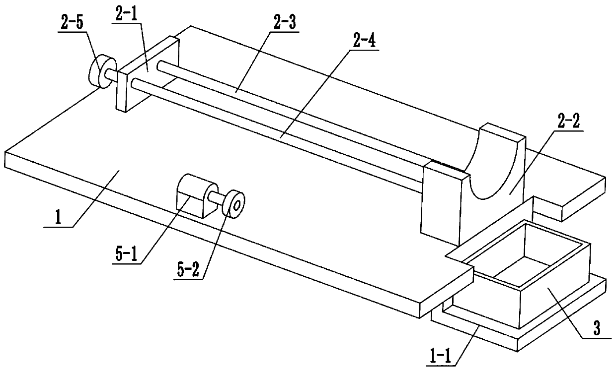
[0031] Combine below Figure 1-11 To illustrate this embodiment, the feed slide 2 includes a side plate 2-1, a wood support seat 2-2, a guide rod 2-3, an external threaded rod 2-4 and a drive pulley 2-5; the side plate 2- 1 and the wood support seat 2-2 are respectively fixedly connected to the left and right ends of the base 1, the two ends of the guide rod 2-3 are respectively fixedly connected to the side plate 2-1 and the wood support seat 2-2, and the external threaded rod 2- The two ends of 4 are respectively connected to the side plate 2-1 and the wood support seat 2-2 through the belt seat bearing rotation, and the transmission pulley 2-5 is fixedly connected to the left end of the external threaded rod 2-4, and the transmission pulley 2-5 is connected to the intermittent feeder. The feeding mechanism 6 is connected by belt transmission; the top surface of the wood support seat 2-2 is provided with a semicircular groove; the wood fixing slide 4 includes a lower fixing ...

specific Embodiment approach 3

[0032] Combine below Figure 1-11 To illustrate this embodiment, the power device 5 includes a motor I5-1 and a driving pulley 5-2; the motor I5-1 is fixedly connected to the front end of the base 1, and the output shaft of the motor I5-1 is fixedly connected to the driving pulley 5-2. 2. The driving pulley 5-2 is connected to the cutting assembly 7 through a belt drive. When the power device 5 is in use, the motor I5-1 is connected to the power supply and the control switch through a wire and turned on, the motor I5-1 drives the driving pulley 5-2 to rotate around its own axis, and the driving pulley 5-2 drives the cutting assembly 7 jobs.


PUM


Abstract

The invention relates to the field of building material processing equipment, in particular to a wood cutting device for forestry engineering. A rectangular through slot is formed in the middle end ofthe right end of a base; an L-shaped seat plate is fixedly connected into the rectangular through slot; a wood collecting box is placed onto the L-shaped seat plate; a feeding slide base is fixedly connected onto the base; the wood collecting box is positioned below the right end of the feeding slide base; a wood fixed slide base is connected on the feeding slide base; a power device is fixedly connected to the front end of the base; the power device is in transmission connection to a cutting assembly through a belt; and the cutting assembly is fixedly connected to the right end of the base.The wood cutting device can fix wood, and the fixed wood is not liable to deviate, so that wood cutting is more smooth, wood scrap is avoided, and waste of wood resources is avoided; and an intermittent feeding mechanism can automatically feed the fixed wood to cut, so that a constructor is prevented from risk during operation.

Description

technical field [0001] The invention relates to the field of building material processing equipment, in particular to a wood cutting device for forestry engineering. Background technique [0002] With the development of the modern mechanical processing industry, the requirements for cutting quality and precision are constantly improving, and the requirements for improving production efficiency, reducing production costs, and highly intelligent automatic cutting functions are also increasing. At present, when the wood cutters on the market are in use, the user needs to press the wood with his hands to fix the wood when cutting. When the technology is used, the wood is cut by the saw blade, but when there is no mechanical fixation, the wood is easy to shift, thus causing the scrap of the wood, which seriously wastes the wood resources, and the limiting device in the prior art does not It cannot adapt to wood of different sizes, and the scope of application is relatively limit...

Claims


Application Information

Patent Timeline
Patent Type & Authority Applications(China)
IPC IPC(8): B27B5/06B27B5/29B27B29/02B27B25/00
Inventor 杨冬霞
Owner 陈芬芬
Why Eureka
Try Eureka