Battery frame lifting system and lifting method

A technology of lifting system and battery frame, which is applied in the direction of electric vehicles, electric power devices, circuits or fluid pipelines, etc. It can solve problems such as stagnation, insufficient stability and flexibility of lifting and replacement operations, and inconvenient operation of battery maintenance and replacement, etc., to achieve high efficiency. Replacement, easy mass production and post-maintenance, fast, stable and flexible lifting operation

Inactive Publication Date: 2019-05-10
于小兵
View PDF9 Cites 2 Cited by
  • Summary
  • Abstract
  • Description
  • Claims
  • Application Information

AI Technical Summary

Problems solved by technology

[0003] The present invention provides a faster lifting operation to solve the current situation that existing new energy electric vehicle battery replacement is not stable enough and flexible enough to easily cause faults such as stagnation, and is likely to cause inconvenience to subsequent battery maintenance and replacement operations. Stable and flexible, it is not easy to cause faults such as jamming, and it provides a better safety guarantee for the battery frame lifting system and lifting method for subsequent battery replacement and maintenance

Method used


Image

  • Battery frame lifting system and lifting method
  • Battery frame lifting system and lifting method
  • Battery frame lifting system and lifting method

Examples


Embodiment 1

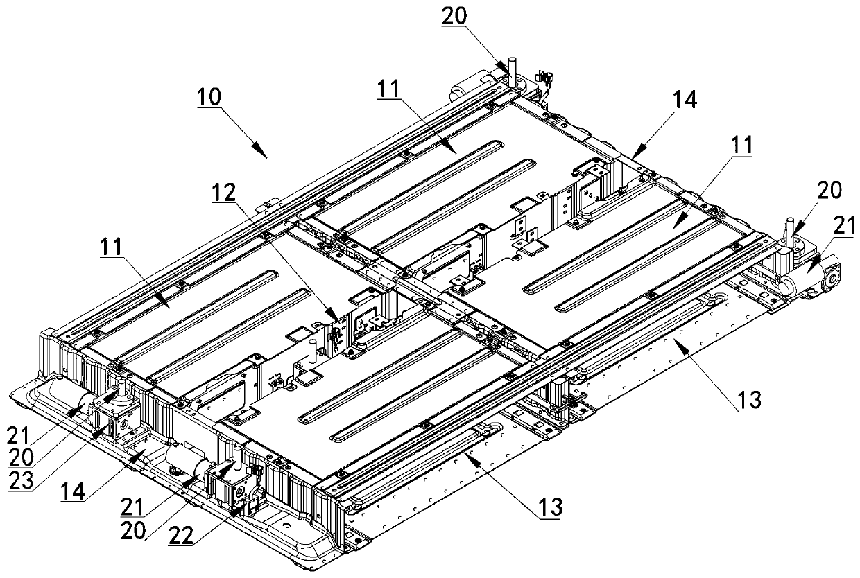
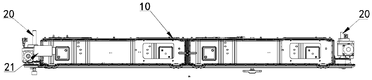
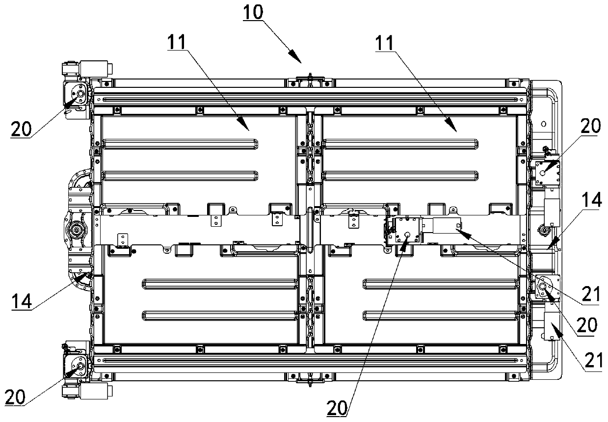
[0067] figure 1 , figure 2 , image 3 In the shown embodiment, a battery frame lifting system includes a battery frame 10, at least two lifting drive mechanisms are arranged between the battery frame and the vehicle body platform, and the lifting drive mechanisms each include a motor, and the motor is started to control the battery frame. The lower side of the vehicle body platform is raised or lowered, and at least one lifting drive mechanism is provided on the front and rear sides of the battery frame, and the motor is fixed to the battery frame or the vehicle body platform. The lowering drive mechanism also includes a reduction box arranged on the motor. The reduction box is provided with a worm gear linked with the output shaft of the motor and a worm cooperating with the worm gear. One of the platforms is fixed, the motor is fixed to the other of the battery frame and the body platform, and the motor is activated to move the motor up and down the worm. Hall sensors ar...

Embodiment 2

[0070] Figure 4 In the shown embodiment, a plurality of lifting drive mechanisms adopt electric push rods 30; the electric push rods 30 are driven and controlled by motors that drive the electric push rods, and the motors are activated to make the electric push rods expand and contract to realize the up and down movement of the battery frame; The rod is connected and fixed with the body platform of the new energy electric vehicle, and the top of the electric push rod and / or the top of the worm gear is connected and fixed with the battery frame 10 . An electric push rod is respectively arranged on the outside of the two ends of the battery frame, and two electric push rods are respectively arranged at the middle position of the ends of the battery frame; an electric push rod is arranged in the middle of the battery frame between the four battery single frames. Others are identical with embodiment 1.

Embodiment 3

[0072] Figure 5 , Figure 6 , Figure 7 , Figure 8 In the illustrated embodiment, a lifting method for a battery frame lifting system includes the following lifting steps:

[0073] 7-1 Judging whether the instrument panel button signal 40 is detected, if there is a button signal, then enter the next execution step, if there is no button signal, return to continue judging whether the instrument panel button signal is detected;

[0074] 7-2 When there is a key signal, the controller wakes up 41;

[0075] 7-3 Determine the state of the battery frame, and process the battery frame in the pre-rising state 50 and in the pre-falling state 60 respectively;

[0076] 7-4 In the above step 6-3, if it is judged to be in the pre-rising state, drive the lifting drive mechanism in one of claims 1 to 5 to control the battery frame to rise 51;

[0077] 7-5 Detect the PMM signal 52 sent by the lifting drive mechanism;

[0078] 7-6 Determine whether the maximum stroke difference ≥ 20mm53...


PUM


Abstract

The invention discloses a battery frame lifting system and a lifting method. at least two lifting driving mechanisms are arranged between a battery frame and a vehicle body platform, each lifting driving mechanism comprises a motor, the motors are started to control the battery frame to ascend or descend on the lower side of the vehicle body platform, at least one lifting driving mechanism is arranged on each of the front side and the rear side of the battery frame, and the motors are fixed to the battery frame or the vehicle body platform. Each lifting driving mechanism further comprises a reduction gearbox arranged on the motor, a worm gear linked with an motor output shaft and a worm matched with the worm gear are arranged in the reduction gearbox, the worm is vertically arranged, one end of the worm is fixed to one of the battery frame and the vehicle body platform, the motor is fixed to the other one of the battery frame and the vehicle body platform, and the motor is started, sothat the motor to move up and down along the worm. The lifting operation is more rapid, stable and flexible, faults such as clamping stagnation are not easily caused, and a better safety guarantee isprovided for subsequent replacement and maintenance of the battery.

Description

technical field [0001] The invention relates to a new energy electric vehicle, in particular to a battery frame lifting system on the new energy electric vehicle. Background technique [0002] With the country's emphasis on and support for new energy electric vehicles, the new energy vehicle industry has also ushered in vigorous development. However, new energy vehicles are not convenient enough in their follow-up supporting services. For traditional fuel vehicles, they have their own convenient manual refueling and self-service refueling services; although there are many new energy fast charging station supporting services However, the number of fast charging stations for existing new energy electric vehicles is still not sufficient, and it still takes a long time for users to charge electric vehicle batteries each time, which cannot better adapt to the high-speed work and life rhythm of modern society; And there are fewer quick battery replacement services that can match ...

Claims


Application Information

Patent Timeline
IPC IPC(8): B60S5/06
CPCY02T10/70Y02T10/7072
Inventor 于小兵罗旭东于忠胡兴伟王建江
Owner 于小兵
Why Eureka
Try Eureka