High-speed centrifugal compressor based on gas suspension

A centrifugal compressor and high-speed centrifugal technology, which is applied to parts of pumping devices for elastic fluids, liquid fuel engines, mechanical equipment, etc., can solve the problem of poor stability of the bearing-rotor system, affect the service life of the motor, and reduce the use of the motor Efficiency and other issues, to achieve high equipment conversion efficiency, long product life, and improve the effect of rotor speed

Inactive Publication Date: 2019-05-10
HUNAN UNIV
View PDF7 Cites 2 Cited by
  • Summary
  • Abstract
  • Description
  • Claims
  • Application Information

AI Technical Summary

Problems solved by technology

The application of these bearings in high-speed centrifugal compressors has many disadvantages
Compressors supported by hydrodynamic bearings generate high temperatures during high-speed rotation. When the high temperature rises to a certain level, the lubricating oil film of the bearings will rupture, eventually leading to bearing failure; compressors supported by rolling bearings or sliding bearings, in daily life In electrical appliances used in daily life, when the compressor starts, runs and stops repeatedly, friction occurs when the bearing and the shaft contact each other, which reduces the efficiency of the motor and affects the service life of the motor; compressors supported by rolling bearings or sliding bearings need to be lubricated Oil supply, the use process is easy to pollute the working environment; the compressor supported by the aerodynamic pressure bearing, due to the influence of the gas dynamic pressure cross-coupling effect, the stability of the bearing-rotor system supported by it is poor; the compressor supported by the aerostatic pressure bearing Compressors, although reducing friction, require an external gas supply and are not suitable for daily electrical appliances that need to be moved at any time

Method used


Image

  • High-speed centrifugal compressor based on gas suspension
  • High-speed centrifugal compressor based on gas suspension
  • High-speed centrifugal compressor based on gas suspension

Examples


Embodiment Construction

[0025] The present invention will be further described in detail below in conjunction with the accompanying drawings and specific embodiments. However, it can be understood that the following specific embodiments are only preferred technical solutions of the present invention, and should not be construed as limiting the present invention.

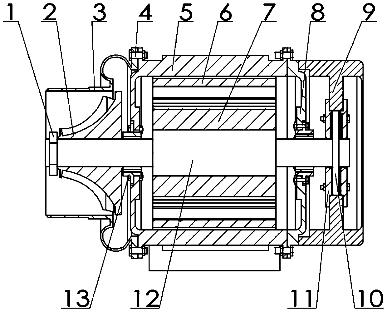
[0026] Such as figure 1 As shown, the centrifugal compressor first includes a shell unit, and the shell includes a compressor housing 5, which is arranged on the surrounding part of the centrifugal compressor for protecting the internal structure of the centrifugal compressor and providing a first tilting pad diameter Installed to the bearing and other parts, the housing can adopt a one-piece structure or a segmented assembly structure, which can be freely arranged by those skilled in the art according to the size of the centrifugal compressor.

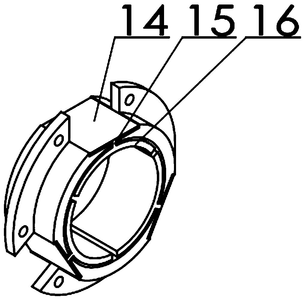
[0027] The shell unit firstly included in the centrifugal compressor also includes a tilting p...


PUM


Abstract

The invention discloses a high-speed centrifugal compressor based on gas suspension. The high-speed centrifugal compressor based on gas suspension comprises a shell unit, an impeller unit and a transmission unit, wherein the shell unit is used for protecting an internal structure of a compressor body, the impeller unit comprises an impeller and an impeller housing, the impeller can be driven to rotate by a rotary shaft, a shaft of the transmission unit is fixedly installed on the impeller, and electric current is applied to a stator winding to drive the shaft to rotate. The transmission unit comprises a tilting bush radial bearing and a tilting bush thrust bearing. The tilting bush radial bearing comprises a PZT, a straight beam, a flexible web and a tilting bush. Voltage is applied to thePZT to make the tilting bush generate high-frequency vibration, and gas film is formed between the tilting bush radial bearing and the shaft, and between the tilting bush thrust bearing and the a thrust plate to provide supporting. The compressor body is lubricated by air without supplied oil for lubrication, and the conversion efficiency of equipment is high; the bearings make no direct contactwith the shaft, the service life of a product is long, and repeated starting and stop can be achieved; a system can be kept running at a high speed stably by controlling voltage; and no supply of static pressure external gas is needed, and the compressor can be used in a device which moves at any time.

Description

technical field [0001] The invention relates to a high-speed centrifugal compressor, and mainly aims at improving the bearing-rotor system of the existing low-power high-speed centrifugal compressor. Background technique [0002] A centrifugal compressor is a machine used to compress gas to increase its pressure or transport gas. It is widely used in various departments of chemical enterprises, and is also used in daily electrical appliances, such as hair dryers, vacuum cleaners, etc. [0003] The compressor of the present invention is a low-power high-speed centrifugal compressor, which is mainly used in daily portable electrical appliances. In the currently disclosed low-power high-speed centrifugal compressors, most of the bearings used are traditional bearings, and a small number of them use air bearings. The application of these bearings in high speed centrifugal compressors suffers from a number of disadvantages. Compressors supported by hydrodynamic bearings generat...

Claims


Application Information

Patent Timeline
Patent Type & Authority Applications(China)
IPC IPC(8): F04D29/056F04D29/063F04D17/10
Inventor 杨思永石明辉李文俊
Owner HUNAN UNIV
Why Eureka
Try Eureka