Automobile engine damping device

A technology of automobile engine and shock absorber, which is applied in power units, jet propulsion devices, internal combustion propulsion devices, etc., can solve the problems of short life and easy damage of the engine, and achieve the effect of high-efficiency shock absorption.

Inactive Publication Date: 2019-05-10
李明宸
View PDF8 Cites 2 Cited by
  • Summary
  • Abstract
  • Description
  • Claims
  • Application Information

AI Technical Summary

Problems solved by technology

However, the existing automobile engine is not equipped with a shock absorber, and the long-term

Method used


Image

  • Automobile engine damping device
  • Automobile engine damping device
  • Automobile engine damping device

Examples


Embodiment 1

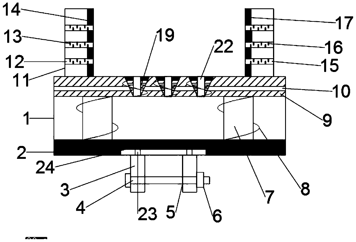
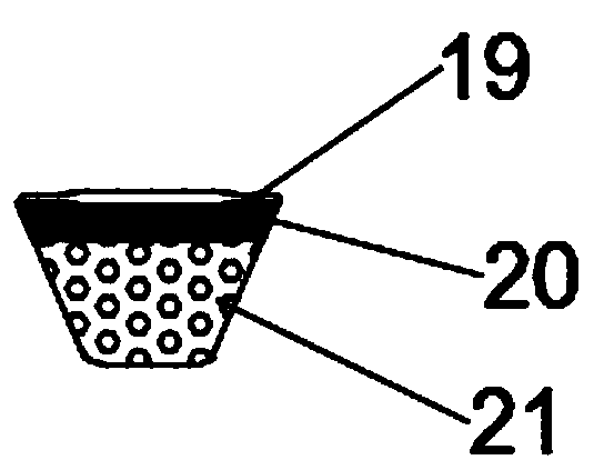
[0022] see figure 1 and image 3 , in an embodiment of the present invention, an automobile engine shock absorber includes a first support body 1, a first buffer layer 2, a splint 3, a second support body 9 and a shock absorbing block 19, and the first support body 1 The bottom is provided with a first cushioning layer 2, which is filled with a foam cushioning material inside the first cushioning layer 2 to play a shock-absorbing effect. The middle part of the first cushioning layer 2 is provided with a groove 24, and the inside of the groove 24 A slide block 23 for sliding connection is provided, and a splint 3 fixedly connected is provided below the slide block 23, and a bolt hole 5 is provided on the splint 3, and the bolt hole 5 is threadedly matched with the bolt 4, and the right end of the bolt 4 is provided with a The nut 6 passes through the bolt hole 5 through the bolt 4, and uses a wrench to tighten the two splints 3, thereby fixing the device on the car.

[0023] ...

Embodiment 2

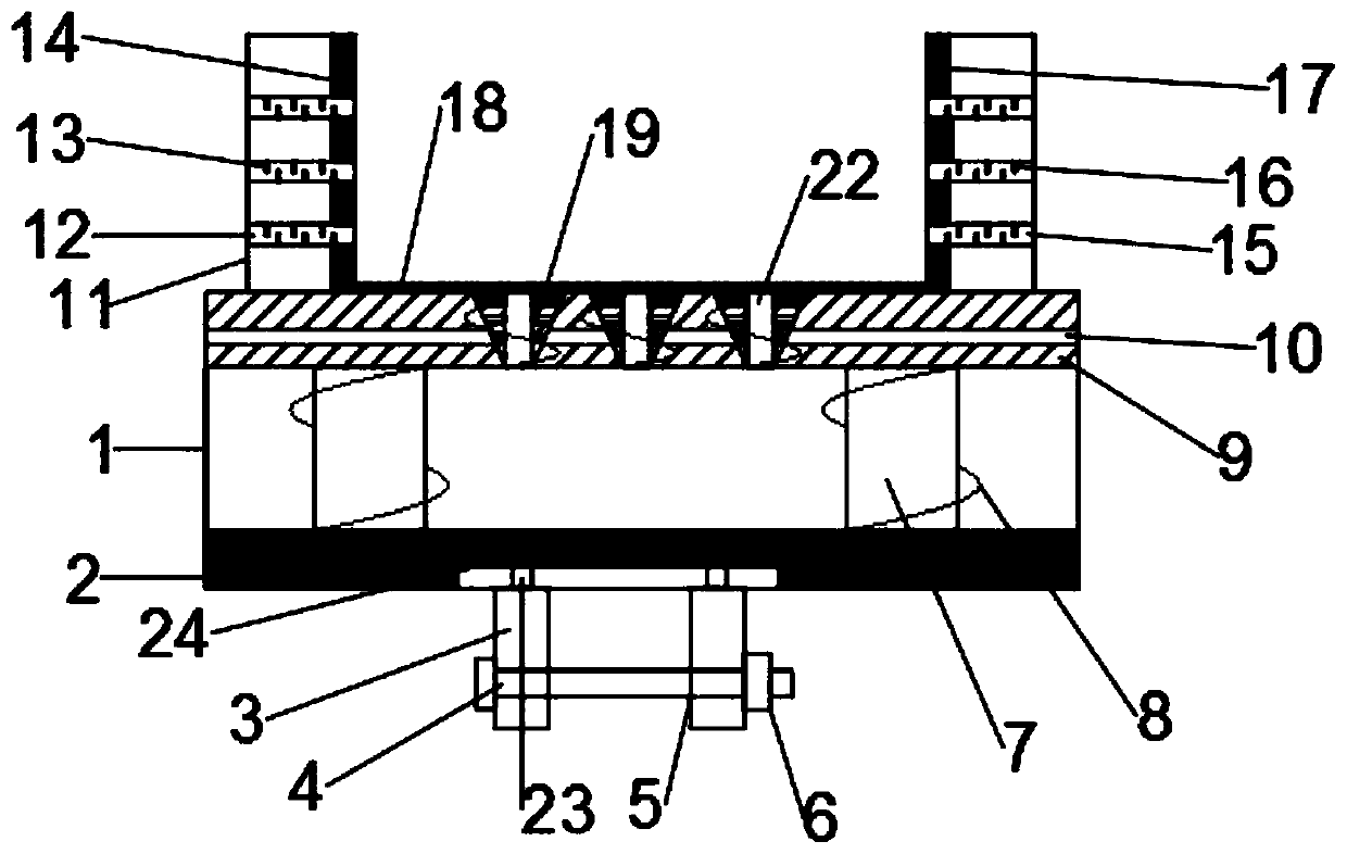
[0029] see figure 2 and 3 , in an embodiment of the present invention, an automobile engine shock absorber includes a first support body 1, a first buffer layer 2, a splint 3, a second support body 9 and a shock absorbing block 19, and the first support body 1 The bottom is provided with a first cushioning layer 2, which is filled with a foam cushioning material inside the first cushioning layer 2 to play a shock-absorbing effect. The middle part of the first cushioning layer 2 is provided with a groove 24, and the inside of the groove 24 A slide block 23 for sliding connection is provided, and a splint 3 fixedly connected is provided below the slide block 23, and a bolt hole 5 is provided on the splint 3, and the bolt hole 5 is threadedly matched with the bolt 4, and the right end of the bolt 4 is provided with a The nut 6 passes through the bolt hole 5 through the bolt 4, and uses a wrench to tighten the two splints 3, thereby fixing the device on the car.

[0030] Furthe...

Embodiment 3

[0037] An automobile engine auxiliary installation device includes the automobile engine shock absorbing device.

[0038] The working principle of the present invention is: the right end of the bolt 4 is provided with a nut 6, the bolt 4 passes through the bolt hole 5, and the two splints 3 are tightened with a wrench, so that the device is fixed on the automobile, the first cushioning layer 2, the elastic The rod 7, the first spring 8, the second support body 9 and the shock absorber 19 play the role of buffer protection, the first air outlet channel 10, the second air outlet channel 22 and the air outlet hole 21 cooperate with each other to play a heat dissipation effect, and the second channel The air holes 15 also play a role in heat dissipation, while the second stoppers 16 are arranged at intervals, which can play the role of noise reduction, and the first rubber pad 14 and the second rubber pad 17 can be compressed, thereby better fixing and protecting different parts. si...


PUM


Abstract

The invention discloses an automobile engine damping device, relates to the technical field of engine production, and mainly solves the problem of short service life caused by engine vibration. The automobile engine damping device comprises a first support body, a first buffering layer, clamp plates, a second support body and a damping block, wherein the first buffering layer is arranged on the bottom of the first support body, the first buffering layer is filled with a foamed buffering material, the middle of the first buffering layer is provided with a groove, sliders connected in a slidingmanner are arranged in the groove, the clamp plates fixedly connected are arranged on the lower portions of the sliders, elastic rods are symmetrically arranged in the first support body in a left andright manner, first springs are arranged at the outer sides of the elastic rods in a sleeving manner, and the second support body is arranged above the first support body. The structure of the automobile engine damping device has a multi-buffering effect, thereby having an efficient damping effect, and at the same time, can carry out silencing cooling and fix and protect different sizes of engines.

Description

technical field [0001] The invention relates to the technical field of engine production, in particular to an automobile engine shock absorber. Background technique [0002] An engine is a machine that can convert other forms of energy into mechanical energy, including internal combustion engines (gasoline engines, etc.), external combustion engines (Stirling engines, steam engines, etc.), electric motors, etc. For example, internal combustion engines usually convert chemical energy into mechanical energy. The engine is not only applicable to the power generation device, but also refers to the whole machine including the power device (such as: gasoline engine, aero engine). The engine was first born in the UK, so the concept of the engine also comes from English, and its original meaning refers to the kind of "mechanical device that generates power". [0003] The history of the generation and development of the engine, it has gone through three development stages of steam ...

Claims


Application Information

Patent Timeline
IPC IPC(8): F16F15/08F16F15/02B60K5/12
Inventor 李明宸
Owner 李明宸
Why Eureka
Try Eureka