Special instantaneous power detection circuit for electro-acupuncture therapy apparatus, and design method of instantaneous power detection circuit

A technology of instantaneous power and detection circuit, applied in the direction of electric power measurement by applying digital technology, can solve problems such as low accuracy, inability to meet the traceability of electroacupuncture therapeutic apparatus, and inability to detect the instantaneous power of electroacupuncture therapeutic apparatus in real time, etc. Accuracy, ensure accuracy, and improve the effect of detection accuracy

Inactive Publication Date: 2019-05-10
CHINA JILIANG UNIV
View PDF5 Cites 0 Cited by
  • Summary
  • Abstract
  • Description
  • Claims
  • Application Information

AI Technical Summary

Problems solved by technology

Testing institutions generally use oscilloscopes and multimeters to detect the waveforms output by electroacupuncture therapeutic instruments, but this method has the following disadvantages: first, the accuracy of oscilloscope detection of electroacupuncture peak-to-peak values ​​is not high, which cannot meet the traceability of electroacupuncture therapeutic instruments;

Method used


Image

  • Special instantaneous power detection circuit for electro-acupuncture therapy apparatus, and design method of instantaneous power detection circuit
  • Special instantaneous power detection circuit for electro-acupuncture therapy apparatus, and design method of instantaneous power detection circuit
  • Special instantaneous power detection circuit for electro-acupuncture therapy apparatus, and design method of instantaneous power detection circuit

Examples


Embodiment Construction

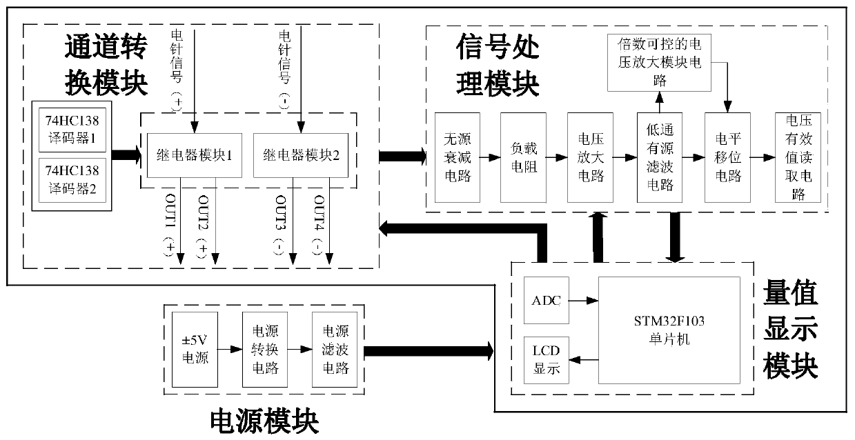
[0037] Such as figure 1 Shown is a detailed block diagram of the instantaneous power detection circuit used in the electroacupuncture treatment instrument. The power supply module includes a ±5V power supply, a power conversion module, and a power filter module. The power supply passes through the power conversion module and the power filter module, and the output is stable ﹢3.3 V voltage is supplied to the single-chip microcomputer, ﹢5V power supply voltage powers the LCD liquid crystal display, and ±5V power supply voltage powers the signal processing module; the channel conversion module includes 74HC138 decoder 1, 74HC138 decoder 2, relay module 1 and relay module 2 , The weak differential signal output by the electroacupuncture treatment instrument is connected to the relay module 1 and the relay module 2. By setting the specific output port of 74HC138 decoder 1, 74HC138 decoder 2 to low level, the relay module 1, relay Module 2 is turned on and off to achieve the effect o...


PUM


Abstract

The invention discloses a special instantaneous power detection circuit for an electro-acupuncture therapy apparatus, and a design method of the instantaneous power detection circuit. The instantaneous power detection circuit comprises a power supply module, a channel conversion module, a signal processing module and a value display module. The power supply module supplies power to the channel conversion module, the signal processing module and the value display module; an electro-acupuncture signal passes through the channel conversion channel firstly, and two to-be-detected signals are measured in real time, so that the effectiveness is guaranteed; and secondly, voltage values at all moments are obtained through the signal processing module, and the value display module converts a voltage peak-to-peak value and a current effective value obtained by the signal processing module into instantaneous power real-time display values. Meanwhile, according to the parameters including the voltage peak-to-peak value and the current effective value needed for detection of the electro-acupuncture therapy apparatus, a load resistor, a passive attenuation circuit, a voltage amplifying circuit,a second-order Butterworth filtering circuit, a level shifting circuit, a voltage effective value reading circuit and a factor-controllable voltage amplifying module circuit in the signal processing module are designed. The instantaneous power detection circuit is specially used for the instantaneous power detection of the electro-acupuncture therapy apparatus, and has the advantages of being accurate in detection, real-time, convenient and the like.

Description

Technical field [0001] The invention relates to an instantaneous power detection circuit and a design method, in particular to an instantaneous power detection circuit and a design method dedicated to an electroacupuncture therapeutic apparatus. Background technique [0002] In the case of a 250Ω load, the electro-acupuncture treatment instrument can generate 0-20V peak-to-peak voltage and 0-10mA current effective value. The accuracy of its value directly affects the life safety of patients, so accurate detection is essential. [0003] According to the market analysis report of the medical industry in 2018, electro-acupuncture treatment devices have been used in hospitals of the top three and above across the country to perform diagnosis and treatment operations such as treatment / adjuvant treatment for patients. However, there is no detection technology for the instantaneous power of electro-acupuncture treatment instruments in China or even in the world. As a result, the Nationa...

Claims


Application Information

Patent Timeline
IPC IPC(8): G01R21/133
Inventor 王梓鉴胡佳成
Owner CHINA JILIANG UNIV
Why Eureka
Try Eureka