
Fingerprint recognition module based on optical structure extracted from collimated light and preparation method thereof

A fingerprint recognition module and optical structure technology, applied in character and pattern recognition, instruments, computing, etc., can solve the problems of low fingerprint recognition accuracy, complex process flow, large overall thickness, etc., to improve the fingerprint recognition accuracy, simplify the Process flow, the effect of improving accuracy

Active Publication Date: 2021-02-02
BOE TECH GRP CO LTD
View PDF9 Cites 0 Cited by
  • Summary
  • Abstract
  • Description
  • Claims
  • Application Information

AI Technical Summary

Problems solved by technology

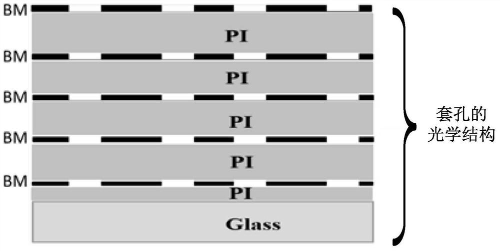
[0006] 1. Since the optical structure layer needs to form a multi-layer BM layer and a PI (polyimide film) layer separating adjacent BM layers, at least 5-6 masking processes are required in the entire process of the fingerprint identification module, 5- 6 times of PI film coating, the process is very complicated
[0007] 2. The multi-layer BM layer and PI layer cause the overall thickness of the optical structure of the fingerprint identification module to reach 100um, which is not conducive to the overall thinning and thinning of the display device, and the overall thickness is greater than 100um, which will also cause a large internal stress of the device, such as Figure 5a As shown, there is a risk of shards from glass bending
[0008] 3. If Figure 5b As shown, in the process of etching round holes in the BM layer, PI residues often appear; because the granular residues in the holes will affect the optical path through the holes, thereby reducing the accuracy of fingerprint recognition
[0009] 4. If Figure 5c As shown, there needs to be a certain deviation between the multi-layer hole pairs, but it is difficult to control the deviation within an appropriate range in the actual production process, resulting in the Miss-align (alignment deviation) problem
[0010] 5. Limited by the influence of 5-layer BM aperture ratio and multi-layer PI transmittance, the light intensity finally reaching the fingerprint recognition sensor is reduced, which seriously reduces the accuracy of fingerprint recognition
[0011] To sum up, the existing fingerprint recognition module based on the optical structure extracted by collimated light has the problems of very complicated manufacturing process, large overall thickness, Miss-align problem, and low fingerprint recognition accuracy.

Method used


Image

  • Fingerprint recognition module based on optical structure extracted from collimated light and preparation method thereof
  • Fingerprint recognition module based on optical structure extracted from collimated light and preparation method thereof
  • Fingerprint recognition module based on optical structure extracted from collimated light and preparation method thereof

Examples


Embodiment Construction

[0053] In order to make the object, technical solution and advantages of the present invention clearer, the present invention will be described in further detail below in conjunction with specific embodiments and with reference to the accompanying drawings.

[0054] Embodiments of the present invention are described in detail below, examples of which are shown in the drawings, wherein the same or similar reference numerals designate the same or similar elements or elements having the same or similar functions throughout. The embodiments described below by referring to the figures are exemplary only for explaining the present invention and should not be construed as limiting the present invention.

[0055]Those skilled in the art will understand that unless otherwise stated, the singular forms "a", "an", "said" and "the" used herein may also include plural forms. It should be further understood that when an element is referred to as being "connected" or "coupled" to another ele...


PUM

PropertyMeasurementUnit
thicknessaaaaaaaaaa

Abstract

The invention discloses a fingerprint identification module based on an optical structure taken out by collimated light and a preparation method thereof. The fingerprint identification module includes: an array of fingerprint identification sensors, and further includes: an An optical structure for extracting direct light; wherein, the optical structure includes: upper and lower nano-grating layers, and a polymer dispersed liquid crystal PDLC layer arranged between the upper and lower nano-grating layers. The application of the present invention can simplify the technological process, reduce the thickness of the fingerprint identification module, avoid the Miss-align problem, and can improve the accuracy of fingerprint identification.

Description

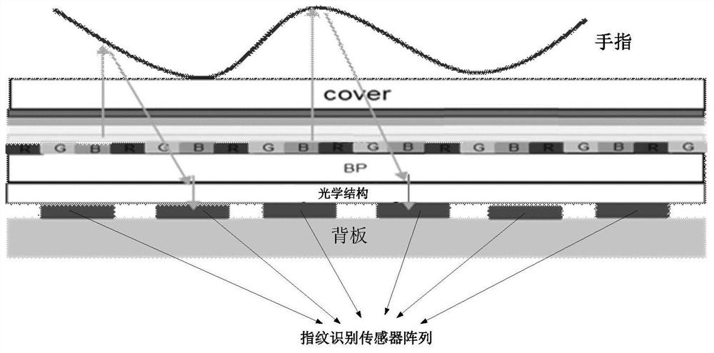
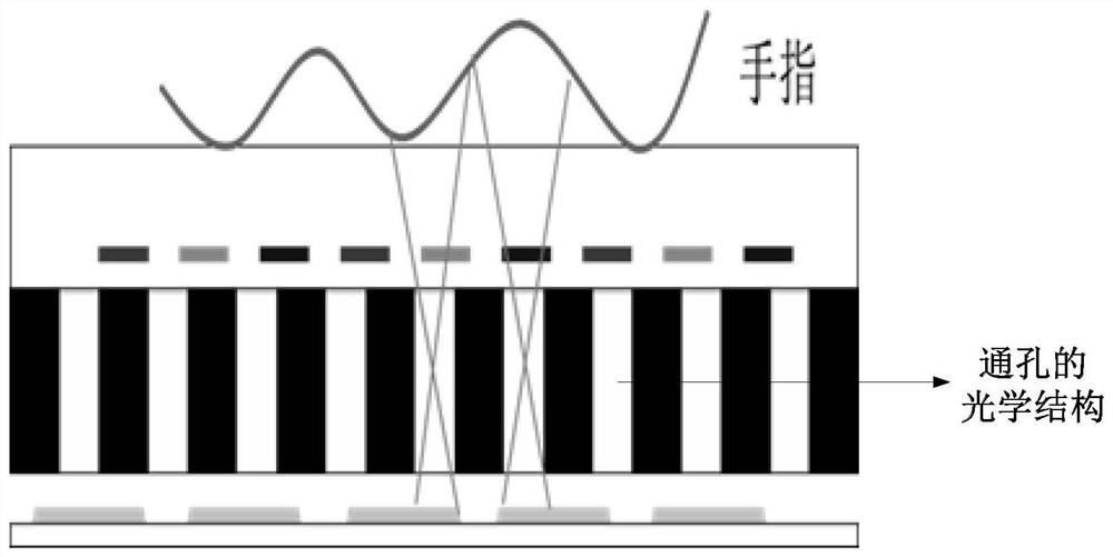
technical field [0001] The invention relates to the technical field of fingerprint identification, in particular to a fingerprint identification module based on an optical structure extracted from collimated light and a preparation method thereof. Background technique [0002] Compared with ordinary screens, full-screen visual effects have higher impact and more stunning display effects, and have become the new favorite of smart display terminals. However, with the increase in screen-to-screen ratio, the design of fingerprint recognition modules based on fingerprint recognition sensors has become an urgent problem for mobile phone terminal manufacturers to solve. [0003] Display devices with full-screen fingerprint recognition technology using collimated light solutions, such as figure 1 As shown, its fingerprint recognition module includes: a fingerprint recognition sensor array and its backplane, and an optical structure layer arranged above the fingerprint recognition s...

Claims


Application Information

Patent Timeline
Patent Type & Authority Patents(China)
IPC IPC(8): G06K9/00G06K9/20
Inventor 岳阳舒适徐传祥于勇李翔杨桐黄敏黄海涛姚琪宋晓欣
Owner BOE TECH GRP CO LTD
Learn More