
Backlight driving method and device and display device

A backlight drive and sub-backlight technology, applied in static indicators, instruments, etc., can solve the problems of reduced brightness of backlight modules, heating of display devices, and increased power consumption, so as to avoid heating, improve overall brightness, and shorten length. Effect

Inactive Publication Date: 2019-05-10
BOE TECH GRP CO LTD +1
View PDF5 Cites 8 Cited by
  • Summary
  • Abstract
  • Description
  • Claims
  • Application Information

AI Technical Summary

Problems solved by technology

However, limited by the driving capability of the driver chip in the related art, if the refresh rate of the head-mounted display device is increased, the time left for the backlight module to emit light will be shortened, which will easily lead to a decrease in the brightness of the backlight module; If the brightness of the backlight is increased by increasing the operating current of the light source in the backlight module, it will easily lead to a series of problems such as heat generation, power consumption increase, and film material wrinkles after the reliability of the head-mounted display device.

Method used


Image

  • Backlight driving method and device and display device
  • Backlight driving method and device and display device
  • Backlight driving method and device and display device

Examples


Embodiment Construction

[0036] In order to further illustrate the backlight driving method and its device, and the display device provided by the embodiments of the present invention, a detailed description will be given below in conjunction with the accompanying drawings.

[0037]At present, the liquid crystal display module used in the head-mounted display panel generally includes a liquid crystal display panel and a backlight module. The backlight module provides backlight to the liquid crystal display panel under the drive of the driver chip, so that the liquid crystal display panel can display. In order to prevent users from being dizzy due to deflection of the liquid crystal, the display of the liquid crystal display panel is inseparable from the use of black insertion technology, that is, inserting a full black frame within two or several adjacent frames, or controlling the backlight module to flash light. Based on this, the above-mentioned backlight module can adopt a splicing structure, that ...


PUM


Abstract

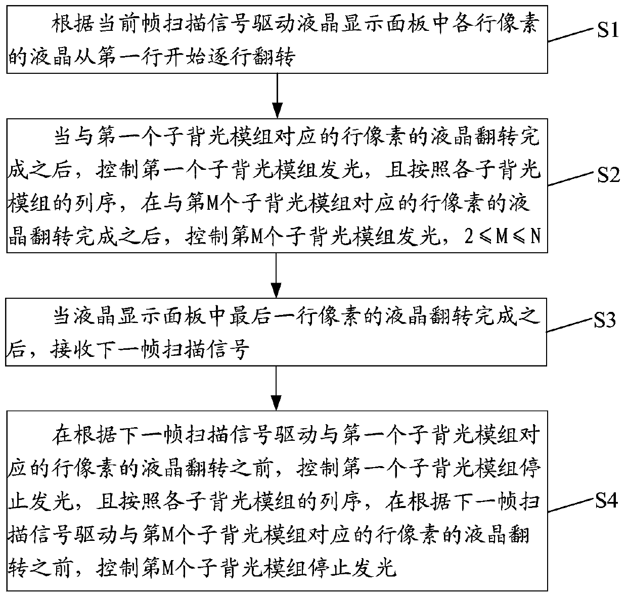
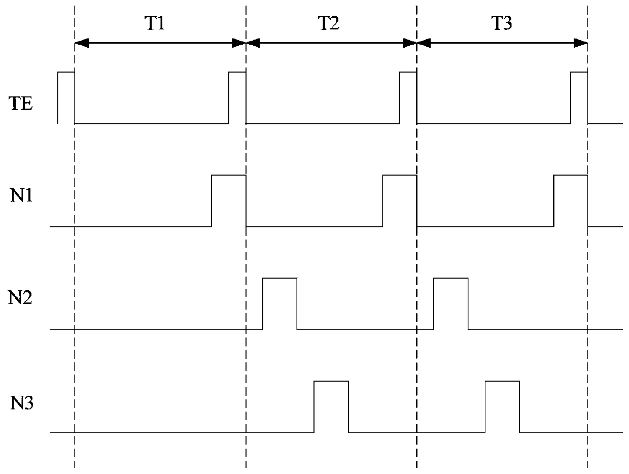
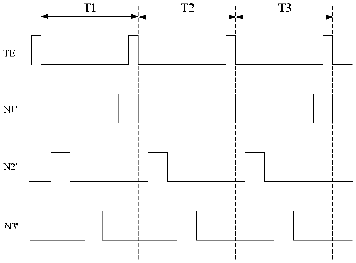
The embodiment of the invention discloses a backlight driving method and device, relates to the technical field of display, and is used for improving the refresh frequency and backlight brightness ofa display device. The backlight driving method comprises the following steps: driving liquid crystals of each row of pixels in a liquid crystal display panel to turn over line by line from a first rowaccording to a current frame scanning signal; After the liquid crystals of the row pixels corresponding to the first sub-backlight module are turned over, controlling the first sub-backlight module to emit light, and according to the column sequence of all the sub-backlight modules, after the liquid crystals of the row pixels corresponding to the Mth sub-backlight module are turned over, controlling the Mth sub-backlight module to emit light; When the liquid crystal of the last row of pixels in the liquid crystal display panel is overturned, receiving a next frame of scanning signal; And controlling the corresponding sub-backlight modules to stop emitting light one by one before driving the liquid crystals of the row pixels corresponding to the sub-backlight modules to turn over in sequence according to the next frame of scanning signal. The backlight driving method and device provided by the embodiment of the invention are used for the liquid crystal display panel.

Description

technical field [0001] The present invention relates to the field of display technology, in particular to a backlight driving method and device, and a display device. Background technique [0002] In recent years, with the continuous development of augmented reality (Augmented Reality, AR for short) and virtual reality (Virtual Reality, VR for short) display technologies, head-mounted display devices have higher and higher requirements for backlight brightness and refresh rate. [0003] At present, head-mounted display devices mostly use a liquid crystal display module for display, and the liquid crystal display module generally includes a liquid crystal display panel and a backlight module; The panel is displayed. However, limited by the driving capability of the driver chip in the related art, if the refresh rate of the head-mounted display device is increased, the time left for the backlight module to emit light will be shortened, which will easily lead to a decrease in ...

Claims


Application Information

Patent Timeline
IPC IPC(8): G09G3/34
CPCG09G3/34
Inventor 马鑫王雪绒陈雷汪志强孙川芮博超王秋里李路康
Owner BOE TECH GRP CO LTD
Learn More