Electromigration testing structure, and testing method

A test structure, electromigration technology, applied in the direction of semiconductor/solid-state device testing/measurement, circuit, electrical components, etc., can solve the problem of inability to judge the change of resistance value

Active Publication Date: 2019-05-10
SHANGHAI HUALI INTEGRATED CIRCUTE MFG CO LTD
View PDF7 Cites 4 Cited by
  • Summary
  • Abstract
  • Description
  • Claims
  • Application Information

AI Technical Summary

Problems solved by technology

The current test structure cannot determine where the resistance changes

Method used


Image

  • Electromigration testing structure, and testing method
  • Electromigration testing structure, and testing method
  • Electromigration testing structure, and testing method

Examples


Embodiment 1

[0035] Embodiment 1 electromigration test structure

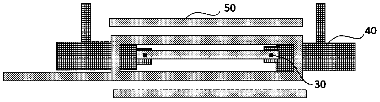
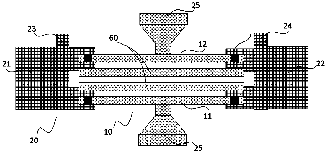
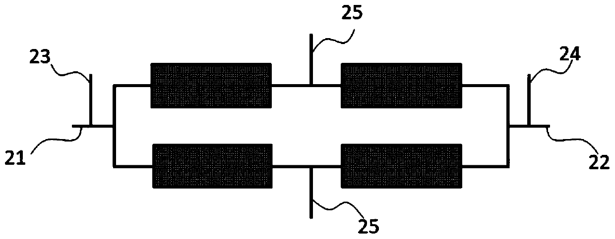
[0036] The electromigration test structure of the present invention includes a metal test structure 10 and a metal connection structure 20; the metal test structure 10 has a head end and an end, and the metal test structure includes at least two metal test lines; the metal connection structure 20 and The head and end of the metal test structure 10 are electrically connected so that the metal test lines in the metal test structure are connected in parallel, and the metal connection structure is also provided with a load current node and a measurement voltage node, and the load current node is used for When the current of the first test metal line and the second test metal line is applied, the voltage measurement node is used to measure the voltage of the parallel connection of the first test metal line and the second test metal line.

[0037] In this embodiment, the metal test structure includes a first test metal line 11 an...

Embodiment 2

[0045] Embodiment 2 Test method based on electromigration test structure

[0046] Step 1, electrically connecting the loading current node of the electromigration test structure to the pad, and the voltage measurement node to the pad. The electromigration test structure includes: a metal test structure 10 and a metal connection structure 20; the metal test structure 10 has a head end and an end, and the metal test structure includes at least two metal test lines; in this embodiment, the The metal testing structure includes a first testing metal line 11 and a second testing metal line 12 , and the resistance values ​​of the first testing metal line 11 and the second testing metal line 12 are the same. The metal connection structure 20 is electrically connected to the head end and the end of the metal test structure 10 so that the metal test lines in the metal test structure are connected in parallel, and the metal connection structure is also provided with a load current node a...


PUM


Abstract

The invention discloses an electromigration testing structure, which comprises a metal testing structure and a metal connection structure, wherein the metal testing structure is provided with a head end and a tail end and comprises at least two metal testing lines; the metal connecting structure is electrically connected with the head end and the tail end of the metal testing structure to enable the metal testing lines in the metal testing structure to be connected in parallel; the metal connection structure is also provided with loading current nodes and measurement voltage nodes, wherein theloading current nodes are used for applying the current of the first testing metal line and the second testing metal line; and the measurement voltage nodes are used for measuring voltage after the first testing metal line and the second testing metal line are connected in parallel. By use of the structure, accuracy for a testing system to judge the time to failure of each testing sample can be improved, and the recommendation accuracy of testing lifetime can be improved. The invention also discloses a testing method for the electromigration testing structure.

Description

technical field [0001] The invention relates to the field of semiconductor circuit design, in particular to an electromigration test structure. The invention also relates to a testing method based on this structure. Background technique [0002] With the shrinking of technology nodes, the technology of metal interconnect electromigration reliability becomes more and more important and more and more challenging. Electromigration (EM) is one of the main failure mechanisms in microelectronic devices. Electromigration causes metallization opens and shorts, which increases device leakage current. After the development of devices to sub-micron and deep sub-micron, the width of metal lines is continuously reduced, the current density is continuously increased, and it is more likely to fail due to electromigration. Therefore, with the progress of the process, the evaluation of EM is highly valued. [0003] The direct cause of electromigration is the movement of metal atoms. When...

Claims


Application Information

Patent Timeline
Patent Type & Authority Applications(China)
IPC IPC(8): H01L23/544H01L21/66
Inventor 朱月芹周柯陈雷刚
Owner SHANGHAI HUALI INTEGRATED CIRCUTE MFG CO LTD
Why Eureka
Try Eureka