Bunker cleaning mechanical hand and coal bunker blockage cleaning robot

A manipulator and arm technology, applied in the field of coal bunker cleaning robots, can solve the problems of easily damaged ground coal bunker, low cleaning efficiency, poor safety, etc., to ensure safety and efficiency, light and compact structure, and improve production efficiency. Effect

Active Publication Date: 2019-05-14
SHANDONG UNIV OF SCI & TECH
View PDF6 Cites 2 Cited by
  • Summary
  • Abstract
  • Description
  • Claims
  • Application Information

AI Technical Summary

Problems solved by technology

[0003] Manual cleaning requires workers to enter the ground coal bunker to clean up the hardened coal seam. The cleaning efficiency is low, and due to the relatively high concentration of gas and carbon monoxide in the coal bunker, it is easy to cause staff poisoning, and there is a safety hazard of explosion
[0004] The hardened coal seam can also be cleaned by blasting. However, this method needs to control the amount of explosives. If the amount of explosives is small, the hardened coal seam cannot be cleaned effectively. If the amount of explosives is large, the coal bunker on the ground will be easily damaged.
[0005] To sum up, in the existing technology, the cleaning efficiency of the coal formation in the ground coal bunker is low, and there are technical problems such as poor safety.

Method used


Image

  • Bunker cleaning mechanical hand and coal bunker blockage cleaning robot
  • Bunker cleaning mechanical hand and coal bunker blockage cleaning robot
  • Bunker cleaning mechanical hand and coal bunker blockage cleaning robot

Examples


Embodiment 1

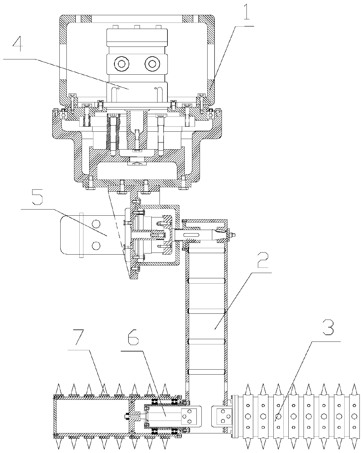
[0072] Embodiment 1 of the present invention describes a clearing manipulator.

[0073] Such as figure 1 As shown, the clearing robot includes a base 1, a robot arm 2 and a scraper 3 connected sequentially from top to bottom.

[0074] Among them, the direction here only refers to the figure 1 The orientation in , may be different from the above orientation when used.

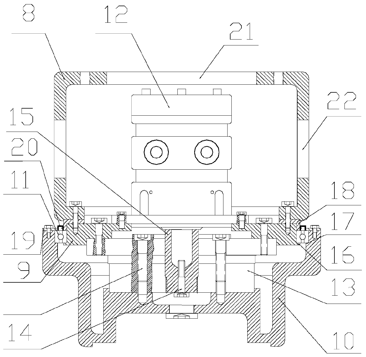
[0075] A first rotary drive mechanism 4 is installed in the base 1 .

[0076] The function of the first rotation driving mechanism 4 is to drive the manipulator arm 2 to rotate in the horizontal direction, which is the first degree of freedom.

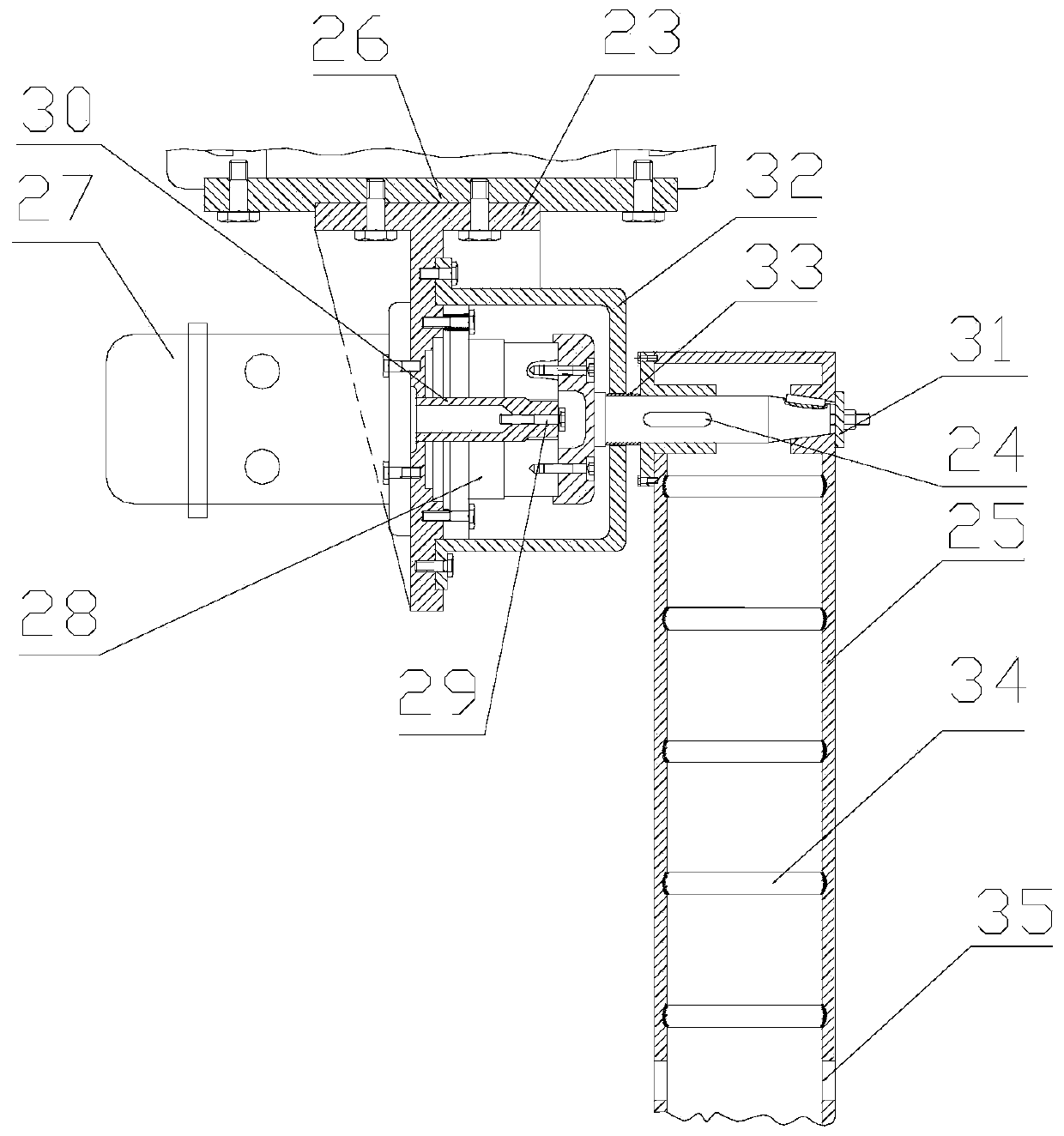
[0077] A second rotary drive mechanism 5 is disposed on the upper end of the manipulator arm 2 .

[0078] The function of the second rotary driving mechanism 5 is to drive the manipulator arm 2 to swing in the vertical plane, which is the second degree of freedom.

[0079] The swing angle, for example, can be within the range of 0°-90°.

[0080] That is, the manipu...

Embodiment 2

[0162] Embodiment 2 describes a coal bunker cleaning robot to meet the requirements of cleaning large ground coal bunkers.

[0163] The coal bunker unclogging robot includes a controller, a gas source and the bunker clearing manipulator in Embodiment 1 above. Wherein, the air source supplies air to the air motors of the above-mentioned rotary drive mechanisms through pipelines.

[0164] In particular, it should be noted that when the air source is the No. 3 air motor 39, its air supply pipeline can pass through the air inlet 35 at the lower part of the arm body 25, then go down through the arm body 25, and connect to the No. 3 air motor 39 on the gas road.

[0165] The controller is connected to the first rotary drive mechanism 4 , the second rotary drive mechanism 5 , and the third rotary drive mechanism 6 respectively through lines, and the controller can realize the three-degree-of-freedom control of the clearing manipulator in the above-mentioned embodiment 1.


PUM


Abstract

The invention discloses a bunker cleaning mechanical hand and a coal bunker blockage cleaning robot. The bunker cleaning mechanical hand comprises a base, a mechanical hand arm and scrabbling devices.The base, the mechanical hand arm and the scrabbling devices are connected in sequence from top to bottom. A first rotation driving mechanism which is used for driving the mechanical hand arm to rotate in the horizontal direction is installed in the base. A second rotation driving mechanism which is used for driving the mechanical hand arm to swing in the vertical plane is arranged at the upper end of the mechanical hand arm in a matched mode. The scrabbling devices are installed at the lower end of the mechanical hand arm and horizontally arranged. Third rotation driving mechanisms which areused for driving the scrabbling devices to rotate around the axes of the scrabbling devices are arranged in the scrabbling devices. Sharp spine portions which are used for cleaning a hardened coal layer away are arranged on the surfaces of the outer sides of the scrabbling devices. The bunker cleaning mechanical hand has three degrees of freedom, is light, exquisite and compact in structure, canrapidly respond to a control instruction, and improves the production efficiency advantageously. The bunker cleaning mechanical hand is utilized and enters a coal bunker to conduct cleaning, and therefore the safety and the high efficiency of the cleaning operation are guaranteed.

Description

technical field [0001] The invention relates to a bin clearing manipulator and a coal bunker clearing robot with the bin clearing manipulator. Background technique [0002] The ground coal bunkers in the prior art often have compaction problems during use, so it is necessary to clean the compacted coal seam in time. There are two commonly used cleaning methods: one is manual cleaning, and the other is cleaning by blasting. [0003] Manual cleaning requires workers to enter the ground coal bunker to clean the hardened coal seam. The cleaning efficiency is low, and due to the relatively high concentration of gas and carbon monoxide in the coal bunker, it is easy to cause staff poisoning, and there is a safety hazard of explosion. [0004] The hardened coal seam can also be cleaned by blasting. However, this method needs to control the amount of explosives. If the amount of explosives is small, the hardened coal seam cannot be cleaned effectively. If the amount of explosives i...

Claims


Application Information

Patent Timeline
Patent Type & Authority Applications(China)
IPC IPC(8): B65D88/68
CPCB65D88/68
Inventor 李玉霞于汝任晓刚景毅张霆张志献吕金虎
Owner SHANDONG UNIV OF SCI & TECH
Why Eureka
Try Eureka