Fill slope frame micro-tensioning supporting anchor plate supporting structure and construction method thereof

A technology of supporting structure and anchor plate, applied in basic structure engineering, excavation, sheet pile wall, etc., can solve the problems of increasing engineering cost, threatening people's life safety, immeasurable economic loss, etc., and achieve important social and economic benefits, The effect of avoiding the waste of land resources and strengthening the practical value of the project

Pending Publication Date: 2019-05-14
LANZHOU UNIVERSITY OF TECHNOLOGY
View PDF0 Cites 4 Cited by
  • Summary
  • Abstract
  • Description
  • Claims
  • Application Information

AI Technical Summary

Problems solved by technology

However, for filling engineering, one of the most important engineering quality issues is the stability of the filling body. In actual engineering, the stability of filling slopes emerges endlessly, and the economic losses caused are even more immeasurable.
For example, a landslide occurs on the side slope of the filling embankment, causing the interruption of the transportation line. If the filling slope of the airport is displaced, it will seriously affect the safety of the airport, and the landslide on the side slope of the filling building threatens the safety of the buildings built on it.
It can be seen that if the above-mentioned important projects have problems due to filling slopes, they will cause certain economic losses at least, and threaten people's lives and safety at worst. Therefore, it is necessary to propose a practical solution to the filling slope problem. Support plan
[0003] Up to now, the existing support methods for fill slopes are mainly the combination of row piles, retaining walls, prestressed anchor plates, and prestressed anchor plates. Although some success has been achieved, these support methods Each has its specific scope of application, and there are some disadvantages
For example: although the support piles in the pile row support can provide greater resistance to ensure the safety of the filling body, and the larger the pile diameter and the longer the pile, the better the support effect, but the support piles are very expensive. The cost is very high; while the general gravity retaining wall support structure is only suitable for slopes with low heights, it is not suitable for high fill slopes, and reinforced soil retaining walls must be reinforced during use Material life issues
At the same time, the prestressed anchor plate uses the contact between the soil and the anchor plate to provide horizontal friction, so that the horizontal force it can provide is determined by the contact area between the anchor plate and the soil. , the large contact area is bound to make the anchor plate large enough, which will also increase the engineering cost; while the prestressed anchor plate depends on the lateral bearing capacity of the contact surface between the fill and the anchor plate. Provide horizontal pull-out resistance, however, the vertical placement of the anchor plate often has problems with its own stability, and the horizontal pull-out resistance it can provide after tilting will be greatly weakened. In addition, the placement requirements during the construction process are high and affect large The efficiency and effect of mechanical compaction; in addition, the use of prestress can certainly improve the support capacity of the support structure in a short period of time, but with the development of time, the prestress will be lost, so the use of prestress in permanent slopes Stress must also pay attention to the loss of prestress
[0004] Obviously, the limitations of existing support methods have restricted the development of filling works, especially high filling works. What kind of technology or new support structures should be used to avoid or reduce the problems existing in existing support structures? Improving the stability of fill slopes, and then increasing the height of fill slopes has become a hot issue in the field of geotechnical engineering.

Method used


Image

  • Fill slope frame micro-tensioning supporting anchor plate supporting structure and construction method thereof
  • Fill slope frame micro-tensioning supporting anchor plate supporting structure and construction method thereof
  • Fill slope frame micro-tensioning supporting anchor plate supporting structure and construction method thereof

Examples


Embodiment Construction

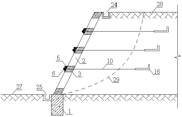
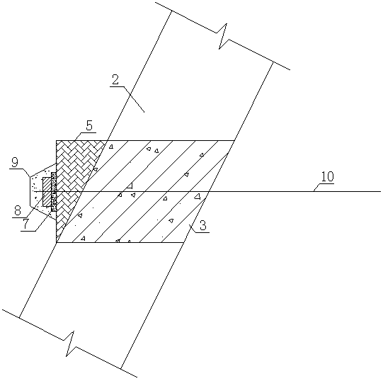
[0039] refer to Figure 1~Figure 6 , the embodiment of the present invention provides a micro-tensioned anchor plate support structure for a fill slope frame, which specifically includes a frame body arranged along the fill slope, which is arranged inside the fill soil body, in the height direction Several supporting anchor plates 16 arranged horizontally in layers and several steel strand stay cables 10 connecting the supporting anchor plates 16 and the frame body. In practical applications, the steel strand cables 10 are arranged horizontally, and the supporting anchor plate 16 is located in the stable soil inside the sliding surface 29 to ensure that the steel strand cables 10 form a stable and sufficient tension on the frame body.

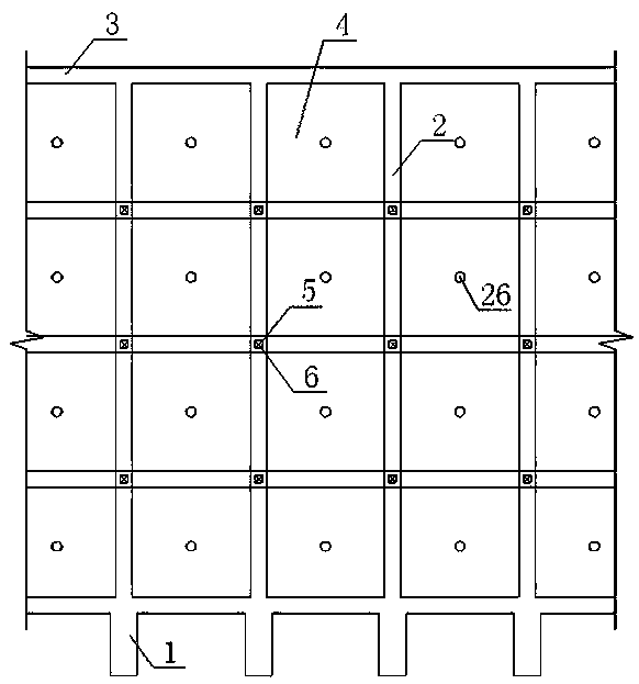
[0040] The above-mentioned frame body specifically includes a soil retaining panel 4 arranged along the fill slope, crossbeams 3 and columns 2 arranged staggeredly on the soil retaining panel 4, and connected to the bottom of the column 2 below...


PUM


Abstract

The invention relates to a fill slope frame micro-tensioning supporting anchor plate supporting structure and a construction method thereof. The supporting structure comprises a frame body arranged along a fill slope surface, a plurality of supporting anchor plates (16) arranged in a fill soil body and arranged in parallel in the height direction, and a plurality of steel strand inhaul cables (10)connecting the supporting anchor plates (16) and the frame body. The frame body comprises a soil retaining panel (4), cross beams (3) and stand columns (2) which are arranged on the soil retaining panel (4) in a staggered mode, foundation piles (1) which are arranged below natural ground (27) at the toe of the fill slope and connected with the bottom ends of the stand columns (2), and cast-in-place concrete which enables the foundation piles, the stand columns, the cross beams and the soil retaining panel to be cast in place into a whole. The supporting structure is simple in form, reasonablein stress and high in practicability, the related construction technology is simple and convenient, the cost is low, and the supporting structure has high engineering practical value and important social and economic benefits and is worthy of large-range application and popularization.

Description

technical field [0001] The invention relates to the technical field of geotechnical engineering support, in particular to a support structure and a construction method for a fill slope frame micro-tensioned anchor plate support structure. Background technique [0002] In recent years, the contradiction between the urbanization process and the area of ​​land available for construction in the mountainous areas of western my country has become increasingly prominent. In order to build airports, residential buildings, roads, etc., engineering construction has to be carried out in the loess area in the northwest, which is full of ravines. manual excavation and filling, resulting in a large amount of filling construction land. However, for the filling project, the most important project quality problem is the stability of the filling body. In actual engineering, the stability of the filling slope emerges endlessly, and the economic losses caused are immeasurable. For example, a la...

Claims


Application Information

Patent Timeline
Patent Type & Authority Applications(China)
IPC IPC(8): E02D17/20E02D5/76
Inventor 杨奎斌朱彦鹏李亚胜王露杨校辉刘鑫凡家恒候喜楠
Owner LANZHOU UNIVERSITY OF TECHNOLOGY
Why Eureka
Try Eureka