Four-frequency differential bandpass filter

A filter and band-splitting technology, applied in microwave and radio frequency fields, can solve the problems of large high-frequency pass-band insertion loss, low out-of-band selectivity, and insufficient depth of four-frequency differential band-pass filter, so as to achieve low insertion loss and enhanced Coupling, enhancing the effect of out-of-band selectivity

Active Publication Date: 2019-05-14
XIDIAN UNIV
View PDF4 Cites 11 Cited by
  • Summary
  • Abstract
  • Description
  • Claims
  • Application Information

AI Technical Summary

Problems solved by technology

Since the research on the four-frequency differential band-pass filter is not deep enough, the performance of the current four-frequency differential band-pass filter needs to be further improved
[0003] For example, in 2017, scholars such as Zhang Shi Xuan published the paper "MultibandBalanced Filters With Controllable Bandwidths Based on Slotline CouplingFeed" in the journal IEEE MICROWAVE AND WIRELESSCOMPONENTS LETTERS (Vol.27, No.11, NOVEMBER 2017), and proposed a coupling-based embedding Th...

Method used


Image

  • Four-frequency differential bandpass filter
  • Four-frequency differential bandpass filter
  • Four-frequency differential bandpass filter

Examples


Embodiment Construction

[0031] The present invention will be further described in detail below in conjunction with the accompanying drawings and specific embodiments.

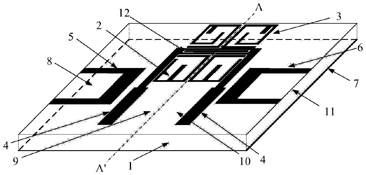
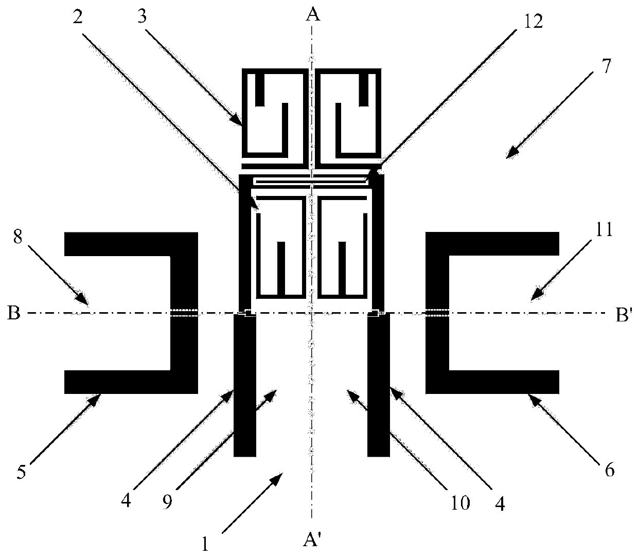
[0032] refer to figure 1 with figure 2 , a four-frequency differential bandpass filter, including a dielectric substrate 1, the upper surface of the dielectric substrate 1 is printed with two first microstrip resonators 2 and two second microstrip resonators 3 that are symmetrical about the axis AA' , two stepped impedance microstrip lines 4 and uniform impedance microstrip lines 12, a U-shaped input microstrip line 5 is printed on one side of the axis AA', and a U-shaped output is printed on the other side of the axis AA' Microstrip line 6; a metal floor 7 is printed on the lower surface of the dielectric substrate 1, and a metal floor 7 is printed on the lower surface of the dielectric substrate 1, and the metal floor 7 is located on one side of the U-shaped input microstrip line 5 side, etched with interconnected first ladder im...


PUM


Abstract

The invention provides a four-frequency differential bandpass filter, and aims to improve the out-of-band selectivity of the four-frequency differential bandpass filter and reduce the in-band insertion loss. The four-frequency differential bandpass filter comprises a dielectric substrate; two first microstrip resonators, two second microstrip resonators, two step impedance microstrip lines and uniform impedance microstrip lines, which are symmetrical about the axis AA', are printed on the upper surface of the dielectric substrate; the uniform impedance microstrip lines are etched with a pair of interdigital coupling linear gaps, and are connected with the tail ends of high impedance microstrip lines of the two step impedance microstrip lines; a U-shaped input microstrip line is printed atone side of the axis AA'; a U-shaped output microstrip line is printed at the other side of the axis AA'; a metal floor is printed on the lower surface of the dielectric substrate; a first step impedance gap line and a first L-shaped step impedance gap line, which are connected, are etched at one side of the U-shaped output microstrip line on the metal floor; and a second L-shaped step impedance gap line and a second step impedance gap line, which are connected, are etched at one side of the U-shaped output microstrip line.

Description

technical field [0001] The invention belongs to the technical field of microwave and radio frequency, in particular to a four-frequency differential bandpass filter, which can be applied to the radio frequency front end of a wireless communication system. Background technique [0002] In recent years, with the rapid development of communication technology, filter, as a key frequency selection device, plays an increasingly important role, and its performance often directly affects the quality of the entire communication system. With the continuous advancement of wireless communication technologies such as global positioning system, wireless local area network, global interoperability microwave access and mobile cellular system, single-frequency filters are no longer practical due to poor adaptability and large size. In order to satisfy multiple functions of multi-band terminal equipment at the same time, multi-band filters have become the mainstream of filter development. On...

Claims


Application Information

Patent Timeline
IPC IPC(8): H01P1/203
Inventor 魏峰岳豪杰徐乐张晓航史小卫
Owner XIDIAN UNIV
Why Eureka
Try Eureka