Motor iron core automatic adhesive lamination high-speed stamping progressive die

A high-speed stamping and automatic technology, applied in the direction of forming tools, manufacturing tools, mechanical equipment, etc., can solve the problems of low production efficiency, reduced motor performance, motor performance and dimensional deformation, so as to improve work efficiency, reduce labor costs, overlap high degree of effect

Inactive Publication Date: 2019-05-14
余姚市奥科五金科技有限公司
View PDF0 Cites 8 Cited by
  • Summary
  • Abstract
  • Description
  • Claims
  • Application Information

AI Technical Summary

Problems solved by technology

[0007] 1. The stamped sheets are scattered all over the place, and they need to be sorted out manually, which is time-consuming and laborious, and the production efficiency is low
[0008] 2. It is necessary to manually superimpose multiple stamping sheets and then place them on the fixture, and then weld them. Manual stacking will easily cause low overlap of adjacent stamping sheets, which will affect the performance and size of the motor after welding.
[0009] 3. The tightness of the punched sheets stacked together is poor, and there is a gap between the sheets, which needs to be completed by a second press with a press. The verticality and flatness of the iron core are poor, and there is a magnetic resistance effect on performance, which reduces the motor. performance

Method used


Image

  • Motor iron core automatic adhesive lamination high-speed stamping progressive die
  • Motor iron core automatic adhesive lamination high-speed stamping progressive die

Examples


Embodiment Construction

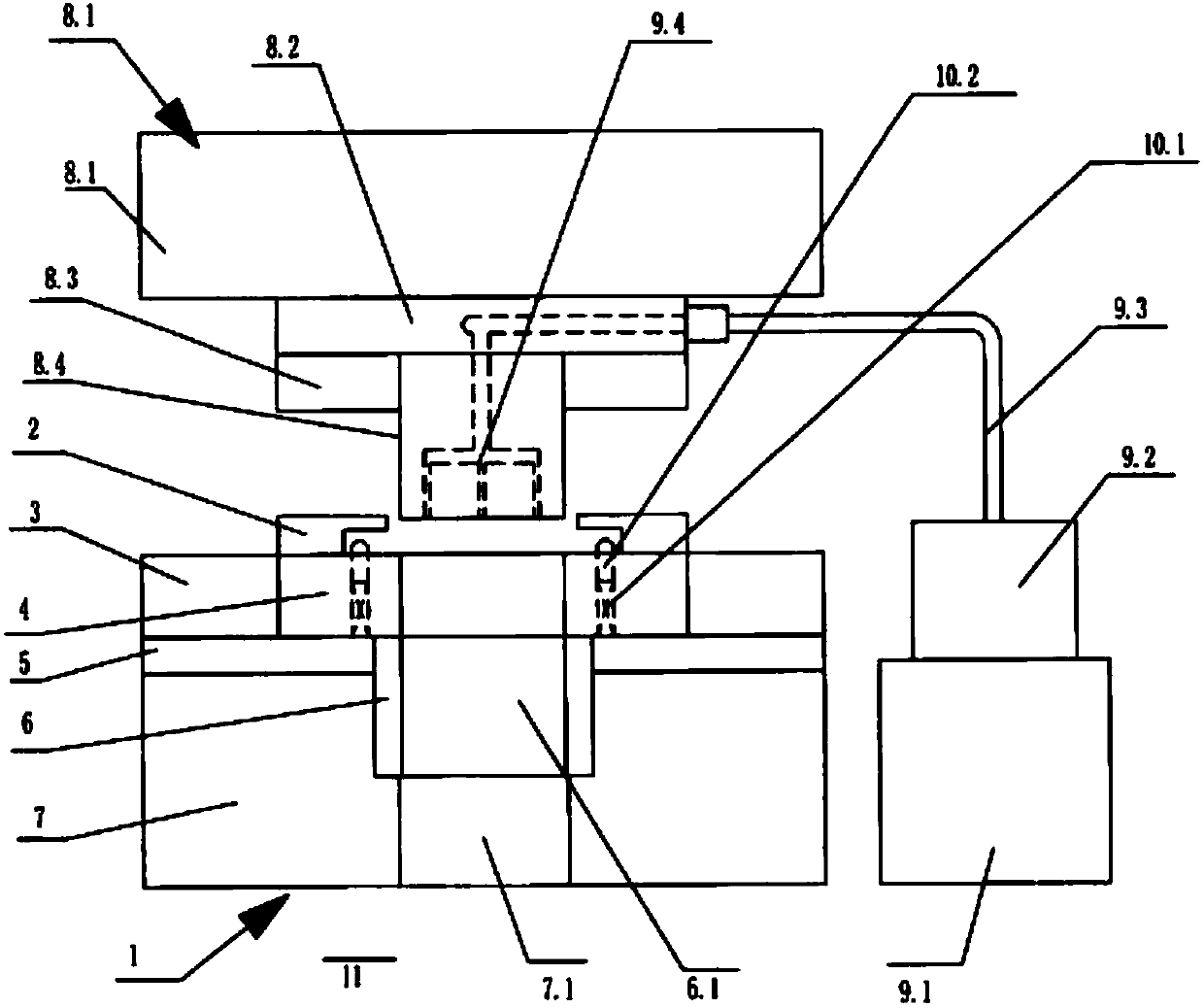
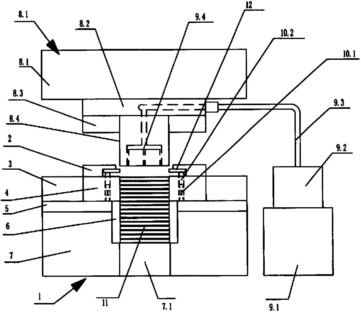
[0020] refer to figure 1 , figure 2 As shown, the motor iron core automatic viscose laminated high-speed stamping progressive die includes an upper die 8, a lower die 1, and a material guide plate 2. The upper die 8 includes an upper die base 8.1, an upper backing plate 8.2, and a punch Backing plate 8.3 and blanking punch 8.4, the lower mold 1 includes a blanking die 3, a die template 4, a die backing plate 5, a locking ring 6, a lower die seat 7, and a blanking die from top to bottom. 3 is installed in the concave template 4, the locking ring 6 is located under the blanking die 3, and the locking ring 6 is provided with locking holes 6.1 in the axial direction to ensure the verticality and parallelism between the punching pieces 11, and the blanking die 3 is opposite to the locking hole 6.1, the inner diameter of the locking ring 6 is smaller than the inner diameter of the blanking die 3, the locking ring 6 is placed in the lower mold base 7, and the product outlet 7.1 is ...


PUM


Abstract

The invention provides a motor iron core automatic adhesive lamination high-speed stamping progressive die. The high-speed stamping progressive die comprises an upper die, a lower die, a material guide plate, an upper die base, an upper base plate, a convex die base plate, a blanking convex die, a blanking concave die, a concave die plate, a concave die base plate, a locking ring and a lower die base, wherein the blanking concave die is arranged in the concave die plate; the locking ring is located below the blanking concave die; the locking ring is axially provided with a locking hole, and the blanking concave die is opposite to the locking hole; the inner diameter of the locking ring is smaller than that of the blanking concave die; the locking ring is placed in the lower die base in a shelved mode; a product outlet is formed below the lower die base, and the lower end of the locking hole is communicated with the product outlet; and the high-speed stamping progressive die further comprises a bonding assembly. The locking ring is arranged below the blanking concave die, so that high perpendicularity and flatness of the iron core and high overlapping degree of adjacent punching pieces are ensured; the locking ring is used for collecting the punching pieces, so that the later labor cost can be greatly lowered; and the bonding assembly is arranged on the upper die, so that synchronous proceeding of punching and bonding is realized, and the working efficiency is greatly improved. The invention belongs to the technical field of die equipment.

Description

technical field [0001] The invention belongs to the technical field of mold equipment, and in particular relates to a progressive die for automatic viscose lamination of motor iron cores and high-speed stamping. Background technique [0002] Stamping die - In cold stamping processing, a special process equipment that processes materials (metal or non-metal) into parts (or semi-finished products) is called a cold stamping die (commonly known as a cold stamping die). Stamping is a pressure processing method that uses a mold installed on a press to apply pressure to the material at room temperature to cause separation or plastic deformation to obtain the required parts. [0003] Stamping die is an indispensable process equipment for stamping production, and it is a technology-intensive product. The quality, production efficiency and production cost of stamping parts are directly related to the design and manufacture of molds. The level of mold design and manufacturing technol...

Claims


Application Information

Patent Timeline
Patent Type & Authority Applications(China)
IPC IPC(8): H02K15/02B21D37/08B23P23/00F16B11/00
Inventor 翁群豪
Owner 余姚市奥科五金科技有限公司
Why Eureka
Try Eureka