
Coal gangue separation sieve, coal gangue sorting part and coal purification gangue removal machine

A technology for separating sieves and gangue, which is applied in solid separation, separating solids from solids with airflow, and filtering and sieving, and can solve problems such as difficulties in pre-screening operations, mixing gangue, and affecting coal preparation work.

Pending Publication Date: 2019-05-17
蔚伟
View PDF9 Cites 4 Cited by
  • Summary
  • Abstract
  • Description
  • Claims
  • Application Information

AI Technical Summary

Problems solved by technology

[0002] A large amount of gangue is mixed in the raw coal mining of coal mines, which not only brings difficulties to other operation steps such as pre-screening, but also a large amount of massive gangue enters the coal preparation operation, which directly affects the coal preparation work and is not conducive to the improvement of product quality.
Commonly used separation methods include manual sorting of large gangue from the mixed coal on the belt conveyor. This method is labor-intensive, the working environment for workers is very difficult, and the efficiency is very low. Omissions and wrong selections often occur Case
Water separation utilizes the different densities of coal and gangue, and relies on the buoyancy of water for separation. This method has a better effect, but the equipment is expensive and the process is complicated, and it requires a lot of water resources. For some rich coal resources, but lack of water It is a major bottleneck of the coal preparation process, which is contrary to the low energy and low consumption in our country at the present stage, and the coal and gangue can only be separated in a fixed factory building, and it is impossible to separate coal and gangue at the coal mine site

Method used


Image

  • Coal gangue separation sieve, coal gangue sorting part and coal purification gangue removal machine
  • Coal gangue separation sieve, coal gangue sorting part and coal purification gangue removal machine
  • Coal gangue separation sieve, coal gangue sorting part and coal purification gangue removal machine

Examples


Embodiment Construction

[0199] Such as Figure 7 to Figure 9 As shown, a gangue separation screen, the shape of the bottom plate of the gangue separation screen 3-1 is a right-angled trapezoid, and the high side of the bottom plate of the gangue separation screen 3-1 is provided with an inclined baffle 3-1-5, The angle between the inclined baffle 3-1-5 and the bottom plate of the gangue separation screen 3-1 is an acute angle, and at least one vibration motor 3-1 is arranged on the outside of the inclined baffle 3-1-5. 1-9, the rotation axis of the vibration motor 3-1-9 is perpendicular to the high side of the bottom plate of the gangue separation screen 3-1, and the rotation axis of the vibration motor 3-1-9 is separated from the gangue The angle between the bottom plates of the sieve 3-1 is greater than 0° and less than or equal to 90°. Viewed from the upper end of the rotating shaft of the vibrating motor 3-1-9, the rotating shaft of the vibrating motor 3-1-9 Rotate clockwise, the long base of th...


PUM


Abstract

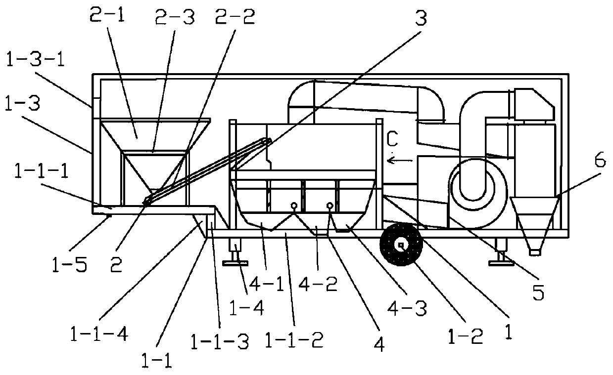
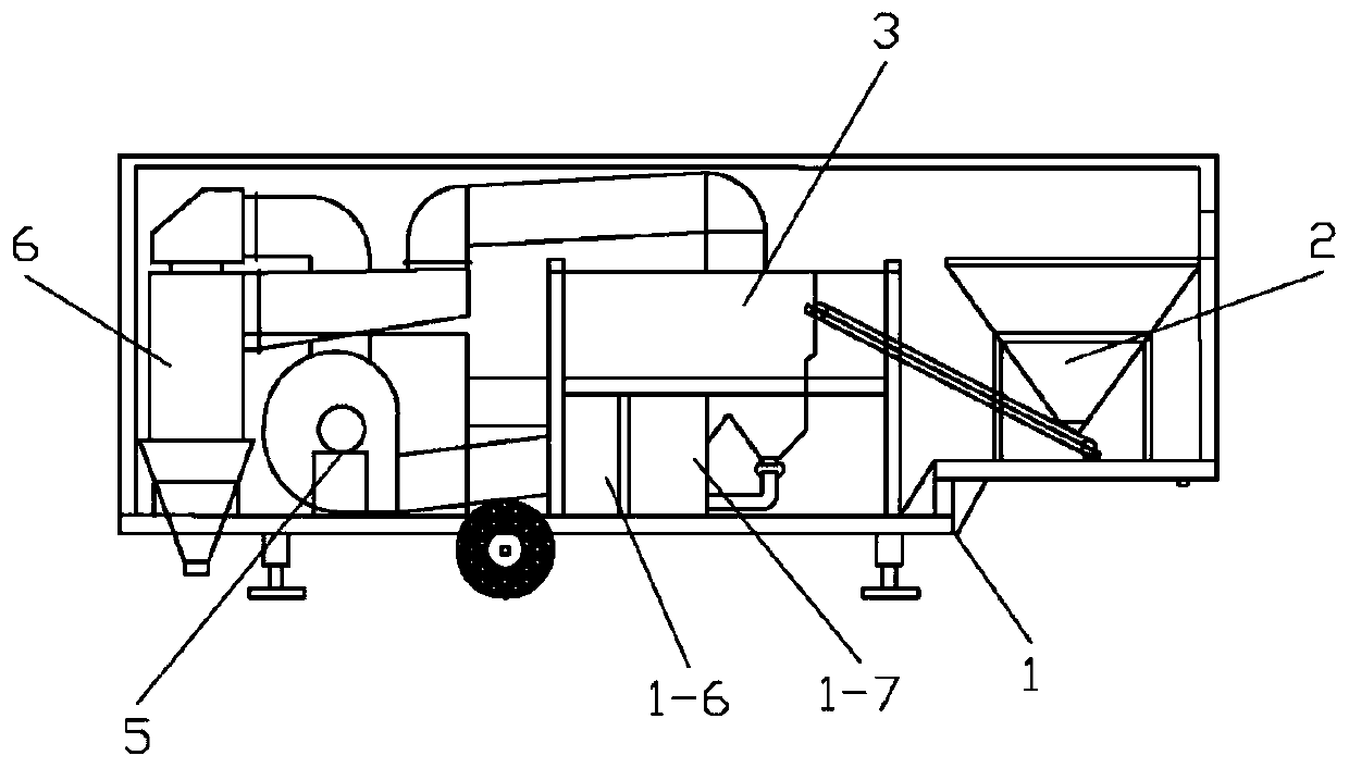
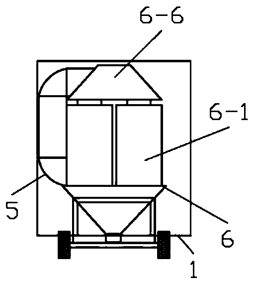
The invention discloses a coal gangue separation sieve, a coal gangue sorting part and a coal purification gangue removal machine. The bottom surface of the coal gangue separation sieve is in a righttrapezoid shape; a plate surface of the coal gangue separation sieve is provided with a plurality of vents; and the upper surface of the coal gangue separation sieve is provided with a plurality of guiding channels. The coal gangue sorting part comprises the coal gangue separation sieve. The coal purification gangue removal machine comprises the coal gangue sorting part, a machine frame part, a feeding part, a discharging part, an air supply part and a dust removing part. Coal mixtures on the coal gangue separation sieve can be separated and distributed through cooperation of vibration of thecoal gangue separation sieve and air blown from the multiple vents, thus, coal can be separated from gangue without using water resources, and meanwhile, the coal and the gangue can be separated undershafts. The coal and the gangue can be separated at coal mines.

Description

technical field [0001] The invention relates to a separating screen, a sorting part and a purifying machine, in particular to a gangue separating screen, a gangue sorting part and a coal purifying and removing machine. Background technique [0002] A large amount of gangue is mixed in the raw coal mining of the coal mine, which not only brings difficulties to other operations such as pre-screening, but also a large amount of massive gangue enters the coal preparation operation, which directly affects the coal preparation work and is not conducive to the improvement of product quality. Commonly used separation methods include manual sorting of large gangue from the mixed coal on the belt conveyor. This method is labor-intensive, the working environment for workers is very difficult, and the efficiency is very low. Omissions and wrong selections often occur Case. Water separation utilizes the different densities of coal and gangue, and relies on the buoyancy of water for sepa...

Claims


Application Information

Patent Timeline
Patent Type & Authority Applications(China)
IPC IPC(8): B07B9/00B07B1/28B07B1/42B07B1/46B07B7/01B04C9/00
Inventor 蔚伟蔚梓琪严冬梅
Owner 蔚伟
Learn More