Waste tire breaker convenient to clean

A technology for crushers and waste tires, which is applied in grain processing, mechanical material recovery, filter screens, etc., can solve the problems of affecting the service life of the crusher, raising the water storage cavity, and being easy to get stuck on the screen mesh, etc. The effect of improving crushing effect, increasing reliability and prolonging service life

Inactive Publication Date: 2019-05-17
杭州大橙知一科技有限公司
View PDF6 Cites 3 Cited by
  • Summary
  • Abstract
  • Description
  • Claims
  • Application Information

AI Technical Summary

Problems solved by technology

[0002] my country is the third largest tire producer in the world, so a large number of waste tire processing equipment has appeared on the market. The waste tire primary shredder currently in use is to put the whole waste tire on the whole tire conveyor and send it to the whole tire shredder for processing. Crushing, through the repeated crushing of the cutter head, and finally the rubber blocks are discharged from the screen. The raw material of the rubber blocks is rubber material with high elasticity. The blockage caused by the rubber block, the existing way to remove the blockage of the screen is to use the air flow and or the water jet method, the air jet is easy to blow up the dust in the crusher, so that the dust is scattered in the air, so the water jet The method is better. In order to reduce the waste of water resources, the water flow is usually recycled. Due to the presence of gravel and dust on the surface of the rubber, a large amount of silt is easy to deposit on the bottom of the water storage, which raises the bottom of the water storage chamber and even affects the crushing. machine life

Method used


Image

  • Waste tire breaker convenient to clean
  • Waste tire breaker convenient to clean
  • Waste tire breaker convenient to clean

Examples


Embodiment Construction

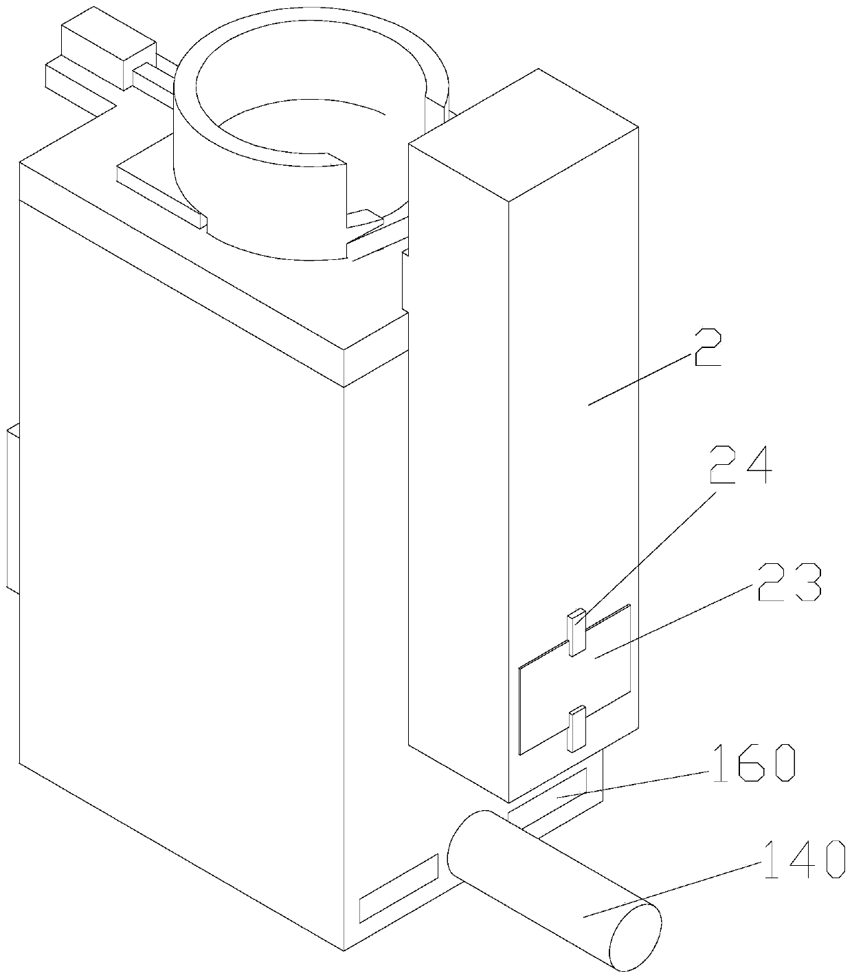
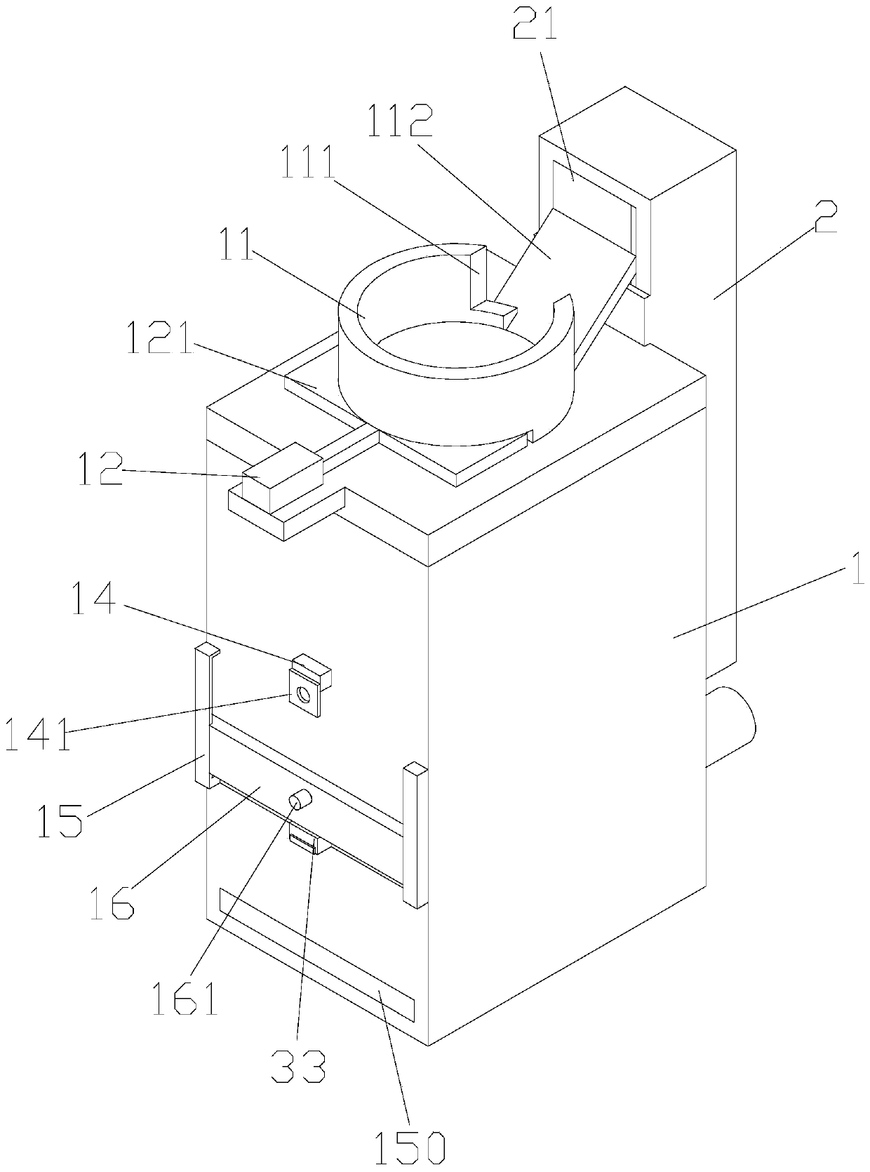
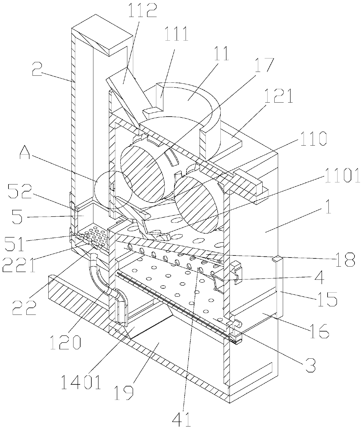
[0022] Such as Figure 1-10 As shown, a waste tire shredder that is easy to clean includes a box body 1, a crushing roller 17 arranged in the box body 1, and a sieve plate 18 arranged below the crushing roller 17, and the crushing rollers are two groups facing each other. The set of rollers, two sets of rollers rotate relatively, which is convenient for crushing waste tires; the top of the box body 1 is provided with a feeding port, and the top of the box body 1 is provided with a feeding port that matches the feeding port. The feed pipe 11, the box body 1 is provided with a material receiving plate 3, the material receiving plate 3 is arranged below the sieve plate 18, and the material receiving plate is provided with a baffle plate 31 to facilitate the collection of rubber blocks and prevent The rubber block falls from the receiving plate; the box body 1 is provided with a spraying device, and the spraying device is arranged below the sieve plate 18, and the side wall of the...


PUM


Abstract

The invention discloses a waste tire breaker convenient to clean. The waste tire breaker comprises a box body, a breaking roller arranged in the box body and a sieve plate arranged below the breakingroller; a feed inlet is formed in the top of the box body; a feed pipe matched with the feed inlet is arranged at the top of the box body; a material receiving plate penetrates through the box body and arranged below the sieve plate; a spraying device is arranged in the box body and arranged below the sieve plate; a water reservoir is arranged at the bottom of the box body and matched with the spraying device; and a cleaning assembly is arranged in the water reservoir. After being sprayed on the sieve plate, a water flow sprayed by the spraying device falls back into the water reservoir underthe action of gravity, and brings dust and other impurities on the sieve plate into the water reservoir together, and sludge at the bottom of the water reservoir is scraped off under the action of thecleaning assembly, so that the bottom of the water reservoir is prevented from being lifted by the sludge, the water storage capacity of the water reservoir is maintained, and the influence of the sludge on the spraying device is avoided.

Description

technical field [0001] The invention belongs to the technical field of harmless recycling of waste rubber, and in particular relates to a waste tire shredder which is easy to clean. Background technique [0002] my country is the third largest tire producer in the world, so a large number of waste tire processing equipment has appeared on the market. The waste tire primary shredder currently in use is to put the whole waste tire on the whole tire conveyor and send it to the whole tire shredder for processing. Crushing, through the repeated crushing of the cutter head, and finally the rubber blocks are discharged from the screen. The raw material of the rubber blocks is rubber material with high elasticity. The blockage caused by the rubber block, the existing way to remove the blockage of the screen is to use the air flow and or the water jet method, the air jet is easy to blow up the dust in the crusher, so that the dust is scattered in the air, so the water jet The method is...

Claims


Application Information

Patent Timeline
Patent Type & Authority Applications(China)
IPC IPC(8): B29B17/04B02C4/08B02C23/10B01D47/06B07B1/46B07B1/55
CPCY02W30/52Y02W30/62
Inventor 陈菁菁
Owner 杭州大橙知一科技有限公司
Why Eureka
Try Eureka