Mechanical processing waste chip treatment device

A processing device and mechanical processing technology, applied in metal processing equipment, water/sewage multi-stage treatment, metal processing machinery parts, etc., can solve the problems of incomplete separation of waste chips and cutting fluid, difficulty in recycling polluted environment, etc., and achieve structural Ingenious, thorough and efficient separation, high efficiency effect

Active Publication Date: 2019-05-17
TIANJIN UNIV OF TECH & EDUCATION TEACHER DEV CENT OF CHINA VOCATIONAL TRAINING & GUIDANCE
View PDF5 Cites 11 Cited by
  • Summary
  • Abstract
  • Description
  • Claims
  • Application Information

AI Technical Summary

Problems solved by technology

[0005] In view of the above situation, in order to overcome the defects of the prior art, the object of the present invention is to provide a machining waste treatment device, which effe

Method used


Image

  • Mechanical processing waste chip treatment device
  • Mechanical processing waste chip treatment device
  • Mechanical processing waste chip treatment device

Examples


Embodiment Construction

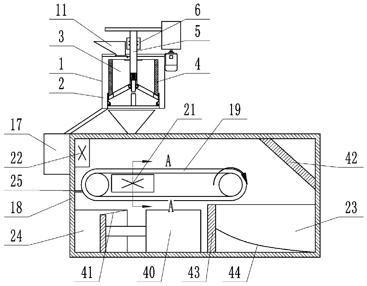
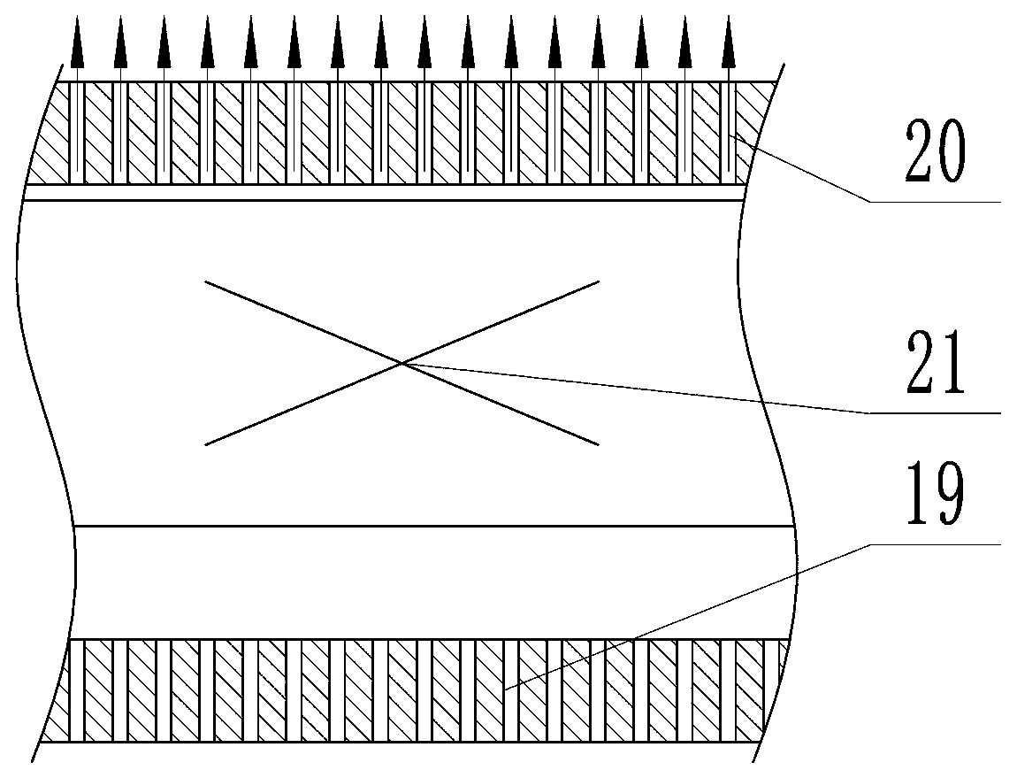
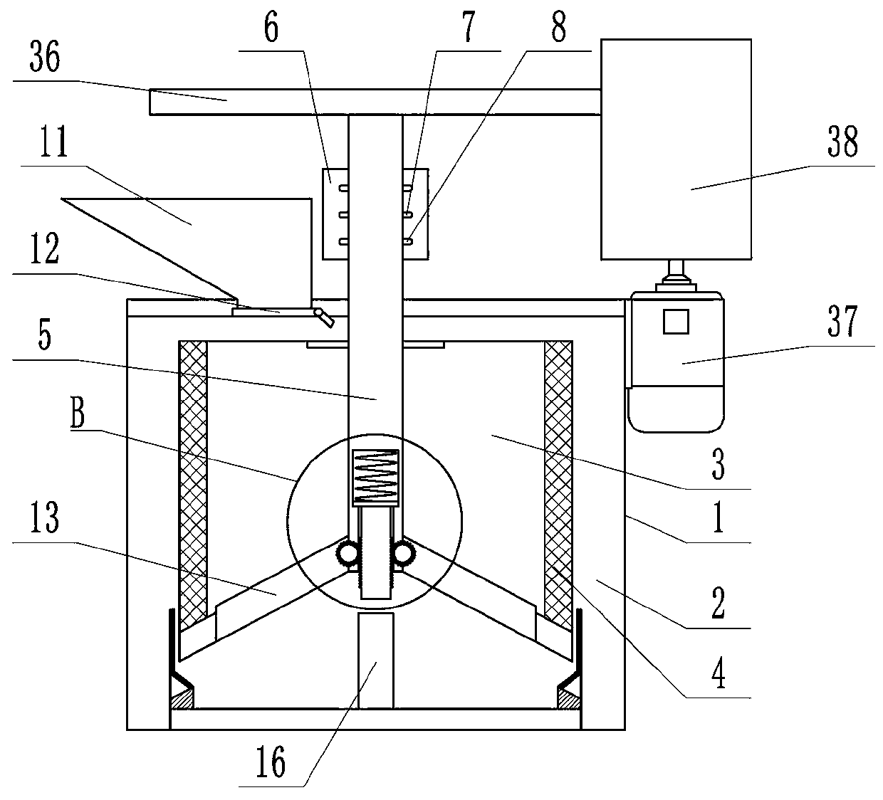
[0021] The following is attached Figure 1 to Figure 13 The specific implementation manner of the present invention will be described in further detail.

[0022] Depend on Figure 1 to Figure 13 It can be seen that a mechanical processing waste treatment device includes a solid-liquid separation bucket and a sundry separation box 18. The solid-liquid separation bucket includes a liquid collection bucket 1 and a dump bucket 3, and the dump bucket 3 is movable and fixed inside the liquid collection bucket 1. The outer wall of the barrel 3 is the first filter screen 4, the rotating shaft 5 of the throwing barrel 3 protrudes from the top of the liquid collecting barrel 1, the outside of the rotating shaft 5 is fixed with a fixed block 6, and the fixed block 6 is provided with a spiral groove, and the rotating shaft 5 protrudes from an insertion screw. The positioning rod 7 in the groove, the positioning rod 7 slides in the spiral groove all the time when the bucket 3 rotates, the...


PUM


Abstract

The invention provides a mechanical processing waste chip treatment device, which effectively solves the problems that the separation of the waste chips and cutting fluid is unthorough in the prior art; after the treatment, environment still can be polluted; the recovery difficulty is great, and the like. The device comprises a solid-liquid separation barrel and a sundry separation box, wherein the solid-liquid separation barrel separates out the chip cutting fluid and collects the cutting fluid into a waste liquid barrel; the rest iron chips and other sundries enter the sundry separation boxto be separated; a magnetic conveying belt is arranged in the sundry separation box; a second fan is fixed on the side wall of the separation box; the sundry box is arranged at one side, far away fromthe second fan, under the magnetic conveying belt; a compression box is arranged under the magnetic conveying belt; a first baffle plate located above the compression box is fixed on the side wall ofthe sundry separation box; the end part of the first baffle plate is in contact with the magnetic conveying belt for knocking off the waste chips on the magnetic conveying belt into the compression box. The structure provided by the invention is ingenious; the throwing mode is used for separating the cutting liquid from the waste chips; the separation is more thorough and efficient; the secondaryseparation is not needed, and the efficiency is higher.

Description

technical field [0001] The invention relates to the technical field of machining, in particular to a machining waste treatment device. Background technique [0002] At present, most factories in China do not pay enough attention to the treatment of cutting fluid containing waste chips. The situation of waste chips being piled up in the open air and cutting fluid being thrown everywhere is becoming more and more serious. [0003] At this stage, most factories have large open-air waste dumps to store a large amount of waste. The workers transport the waste from the machine tool to the stacking site by the waste pick-up trolley and pour them in, and then load them in a unified manner. shipped away. In the process of transporting waste chips, due to the large amount of cutting fluid contained in the untreated waste chips and the incomplete sealing of the trolley, which is easy to leak, it will cause oil leakage and iron filings during the handling and loading process, which wil...

Claims


Application Information

Patent Timeline
IPC IPC(8): C02F9/12B23Q11/00
Inventor 靳刚张开飞李占杰韩建鑫崔良玉
Owner TIANJIN UNIV OF TECH & EDUCATION TEACHER DEV CENT OF CHINA VOCATIONAL TRAINING & GUIDANCE
Why Eureka
Try Eureka