
Narrow-body and all-condition directional drilling machine for coal mine

A technology of directional drilling rigs and all working conditions, which is applied in directional drilling, drilling equipment, earthwork drilling and mining, etc. It can solve the problem that directional drilling rigs cannot meet specific drilling conditions, limit the scope of application of directional drilling rigs, and poor applicability of small and medium mines, etc. problems, to achieve the effect of ensuring comprehensiveness and practicability, applicability, and coverage

Active Publication Date: 2019-05-17
CHINA COAL TECH & ENG GRP CHONGQING RES INST CO LTD
View PDF4 Cites 2 Cited by
  • Summary
  • Abstract
  • Description
  • Claims
  • Application Information

AI Technical Summary

Problems solved by technology

After summarizing many application examples, some shortcomings of the current directional drilling rigs are also found: First, the overall size of the current directional drilling rigs is relatively large, and there are high requirements for the size of the roadway and the drilling site during transportation and use, so It is not suitable for small and medium mines with thin coal seams in the south; secondly, due to the limitation of the current structure of directional drilling rigs, directional drilling rigs cannot meet some specific drilling conditions in coal mines, which limits the scope of application of directional drilling rigs

Method used

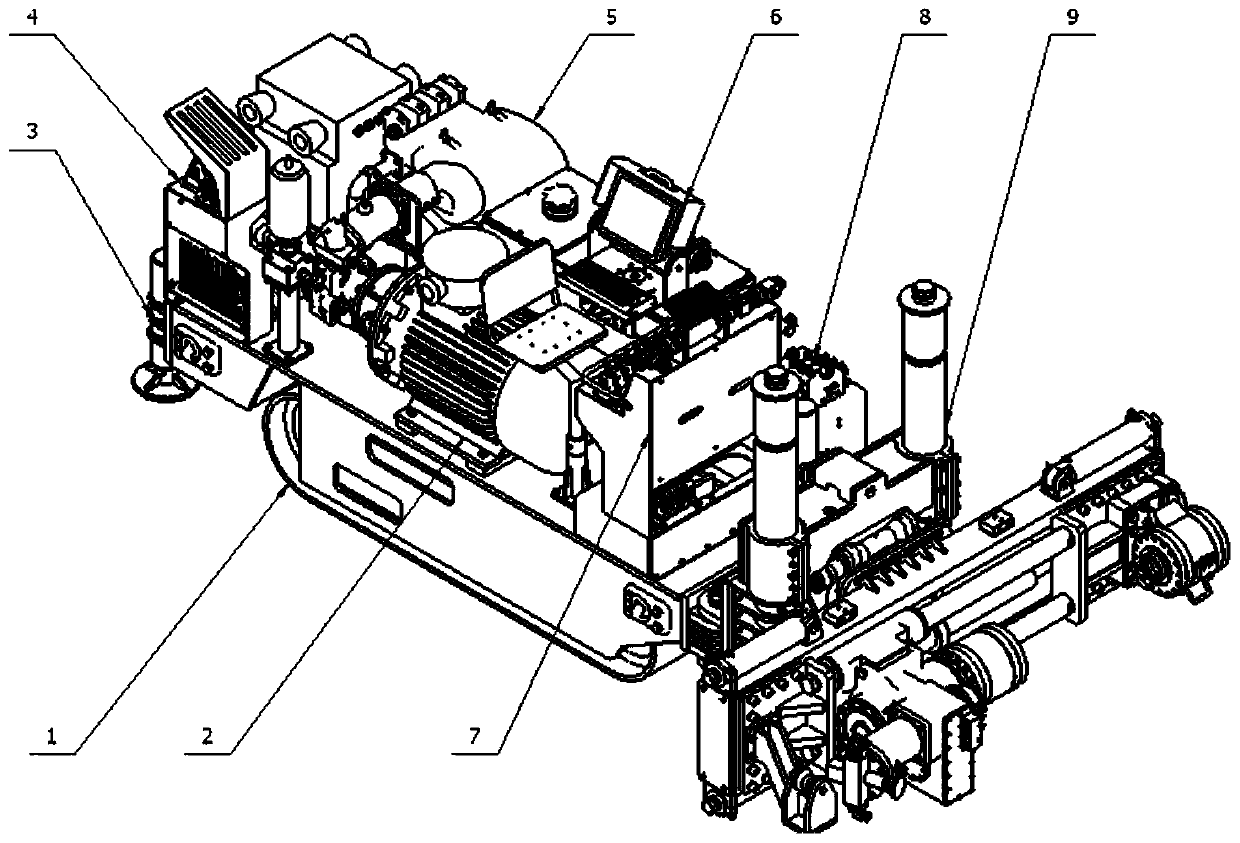

Image

  • Narrow-body and all-condition directional drilling machine for coal mine
  • Narrow-body and all-condition directional drilling machine for coal mine
  • Narrow-body and all-condition directional drilling machine for coal mine

Examples


Embodiment Construction

[0024] Embodiments of the present invention are described below through specific examples, and those skilled in the art can easily understand other advantages and effects of the present invention from the content disclosed in this specification. The present invention can also be implemented or applied through other different specific implementation modes, and various modifications or changes can be made to the details in this specification based on different viewpoints and applications without departing from the spirit of the present invention. It should be noted that the diagrams provided in the following embodiments are only schematically illustrating the basic concept of the present invention, and the following embodiments and the features in the embodiments can be combined with each other in the case of no conflict.

[0025] Wherein, the accompanying drawings are for illustrative purposes only, and represent only schematic diagrams, rather than physical drawings, and should...


PUM


Abstract

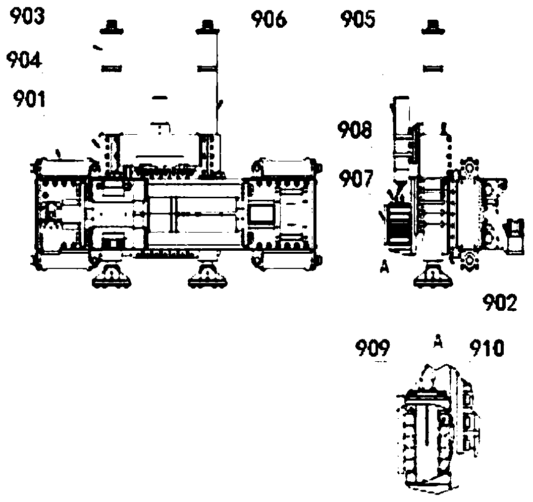
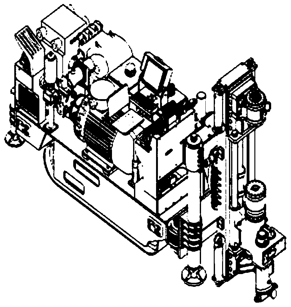
The invention belongs to the field of whole directional drilling machines for coal mine and particularly relates to a narrow-body and all-condition directional drilling machine for coal mine. A motorassembly, a walking anchoring operating platform assembly, a slurry pump assembly, a computer assembly, a drilling machine operating platform assembly and a multi-way valve assembly are arranged on acrawler assembly; two groups of anchoring assemblies are symmetrically arranged at the back part of the crawler assembly; and a machine frame adjusting assembly is arranged at the front part of the drilling machine and is used for adjusting the position and the dip angle of the machine frame. The whole size is more compact, and the structure of the existing main vehicle and a slurry pump vehicle double caterpillar vehicle is optimized into a single caterpillar vehicle, so the narrow-body and all-condition directional drilling machine for coal mine has applicability in the coal transportation and use process with small lane size; and the machine frame structure of the drilling machine can meet the requirements of the drilling processes with different drilling height, multiple azimuth and all condition under the condition that the hole opening height is low enough, so that the comprehensiveness and the practicability of the drilling machine on the requirements of the drilling process areguaranteed, the construction success rate of the directional branch hole is increased and the coverage range of directional drilling is guaranteed.

Description

technical field [0001] The invention belongs to the field of directional drilling rigs used in coal mines, and in particular relates to a directional drilling machine with a narrow fuselage and full working conditions for coal mines. Background technique [0002] At the current stage, with the increase of promotion efforts and the promotion of significant use effects, there are more and more application examples of directional drilling rigs in coal mines, and the demand is also increasing. Due to its unique technical characteristics, directional drilling rigs have played an increasingly important role in the fields of underground gas drainage, water detection and release, and advanced detection in coal mines, improving the production efficiency and production safety of coal mining enterprises. After summarizing many application examples, some shortcomings of the current directional drilling rigs are also found: First, the overall size of the current directional drilling rigs...

Claims


Application Information

Patent Timeline
Patent Type & Authority Applications(China)
IPC IPC(8): E21B7/02E21B7/04E21B15/04E21B44/00
Inventor 闫保永雷丰励王清峰王杰朱利民孟祥辉阳廷军刘思聪叶强波陈泽平郝少楠郭向勇张晓泽
Owner CHINA COAL TECH & ENG GRP CHONGQING RES INST CO LTD
Learn More