Electronic device water cooling system drive pump

A water-cooling system and electronic device technology, applied in the direction of machines/engines, pumps with flexible working elements, pumps, etc., can solve the problems of low output flow and pressure accuracy, limited fluid pressure and fluid circulation capacity, flatness and cut-off effect Poor and other problems, to achieve volumetric energy density and output flow, improve output capacity and control accuracy, good cut-off effect

Active Publication Date: 2019-05-17
ZHEJIANG NORMAL UNIVERSITY
View PDF19 Cites 1 Cited by
  • Summary
  • Abstract
  • Description
  • Claims
  • Application Information

AI Technical Summary

Problems solved by technology

Due to the limited fluid pressure and fluid circulation capacity formed by the proposed micro fan and micro pumping system, and the unsatisfactory heat dissipation and cooling effect, there are certain limitations in practical application. The pressure is greatly affected by the working conditions. Fluid viscosity, temperature and output pressure affect the resonant frequency of the pump by affecting the system damping. When the resonant frequency of the piezoelectric vibrator under specific working conditions deviates greatly from the set excitation frequency, The output flow and pressure of the pump will drop significantly
Therefore, the output performance of the piezoelectric pump at a fixed frequency is not ideal, and the accuracy of the output flow and pressure calculated according to the set driving voltage and frequency is also low; in addition, most of the existing piezoelectric pumps use cantilever beam type The cut-off valve has poor flatness and cut-off effect, which seriously affects the output flow and pressure of the pump

Method used


Image

  • Electronic device water cooling system drive pump
  • Electronic device water cooling system drive pump
  • Electronic device water cooling system drive pump

Examples


Embodiment Construction

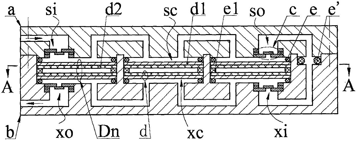
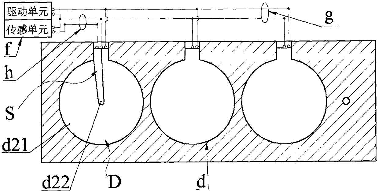
[0020]A water-cooling system drive pump for electronic devices of the present invention consists of a pump cover a, a pump body b, a disc valve c, a transducer Dn, a sealing ring e, an O-ring e', a power supply f, a lead group g and a lead group Two h constitute. The pump cover a is provided with an inlet a1, an orifice a4 with an upper outlet a2 and at least two body platforms a5, and the leftmost body a5 is provided with an upper outlet a8 and an upper inlet a7 connected with the inlet a1, The rightmost body platform a5 is provided with an upper inlet a9 and an upper outlet a10 connected with the upper outlet a2, and the other body platforms a5 are provided with an upper inlet a9 and an upper outlet a8, and two adjacent upper inlets a9 and upper outlets a8 is connected; the pump body b is provided with an outlet hole b1, a cavity b4 with a lower inlet hole b2, and a body cavity b5 with the same number as the body platform a5 and with a wire groove b6 on the side wall, and th...


PUM


Abstract

The invention belongs to the technical field of heat dissipation cooling, and particularly relates to an electronic device water cooling system drive pump. A pump cover and a pump body are provided with inlet and outlet valves composed of butterfly valves. The pump cover is arranged on the pump body. Energy converters are in pressing joint in body cavities of the pump body through pump cover bodytables and seal rings. Each energy converter is composed of an elastic ring and piezoelectric vibrators pasted to the two sides of the elastic ring, wherein each piezoelectric vibrator is formed by pasting a base plate and a piezoelectric plate. Upper pump cavities are formed by the energy converters, the seal rings and the pump cover, lower pump cavities are formed by the energy converters, the seal rings and the pump body, and the upper pump cavities connected in parallel and the lower pump cavities connected in parallel are connected in series. At least one piezoelectric vibrator comprisesa driver and a sensor, a power source outputs the same direct current drive voltage signals to the piezoelectric vibrators and the driver, sensing voltage signals generated by the sensor are utilizedfor judging the piezoelectric vibrator deformation state, and when the sensing voltage reaches the extreme value, the drive voltage of the power source and the piezoelectric vibrator deformation direction are reversed, and piezoelectric vibrator reciprocated bending vibration and fluid one-way flowing are formed through alternated reversing of the drive voltage.

Description

technical field [0001] The invention belongs to the technical field of heat dissipation and cooling, and in particular relates to a driving pump for an electronic device water cooling system. Background technique [0002] In recent years, with the improvement of the integration and miniaturization of sub-products, as well as the continuous improvement of the operating speed and configuration density of electronic components such as chips and integrated circuits, the internal ventilation performance of electronic equipment is continuously declining, and the development of electronic components The heat is constantly rising, and cooling methods such as traditional fans and external heat sinks can no longer meet the actual needs. The cooling and heat dissipation effect of the internal components of electronic equipment has become a key factor restricting its reliability and operational stability. Based on this, people have successively proposed a variety of new air-cooled and w...

Claims


Application Information

Patent Timeline
Patent Type & Authority Applications(China)
IPC IPC(8): F04B43/04F04B53/10
Inventor 姚汤伟常正方毛燕飞宋子怡王淑云杨泽盟张可程光明
Owner ZHEJIANG NORMAL UNIVERSITY
Why Eureka
Try Eureka