An active filter rectifier circuit

A filter rectification, DC control circuit technology, applied in electrical components, adjustment of electrical variables, high-efficiency power electronic conversion, etc., can solve the problem of increasing the cost, volume and manufacturing difficulty of passive components, increasing the electrical stress of switching devices, electromagnetic interference, and increasing filtering. The difficulty of component design and other issues can reduce the number of components, reduce the intermediate DC link, and achieve the effect of voltage stability.

Active Publication Date: 2021-02-02
汲克凤
View PDF7 Cites 0 Cited by
  • Summary
  • Abstract
  • Description
  • Claims
  • Application Information

AI Technical Summary

Problems solved by technology

However, the two-stage power supply scheme has disadvantages such as high cost, large number of components, and complicated control.
In recent years, a single-stage active filter circuit has been proposed in the industry. The single-stage active filter circuit is generally a boost circuit (boost topology), and the current working mode is a discontinuous mode (DCM mode), which has the following disadvantages: ( 1) There are large current spikes in the working current, which increases the electrical stress and electromagnetic interference of switching devices in the circuit
(2) In order to reduce losses and cope with light load conditions, the switching frequency of power devices varies widely, which increases the complexity of control and the design difficulty of filter components
(3) The peak current in intermittent working mode increases the cost, size and manufacturing difficulty of passive components (such as inductors) in the circuit

Method used


Image

  • An active filter rectifier circuit
  • An active filter rectifier circuit
  • An active filter rectifier circuit

Examples


Embodiment Construction

[0016] The specific implementation manner of the present invention will be described in further detail below by describing the best embodiment with reference to the accompanying drawings.

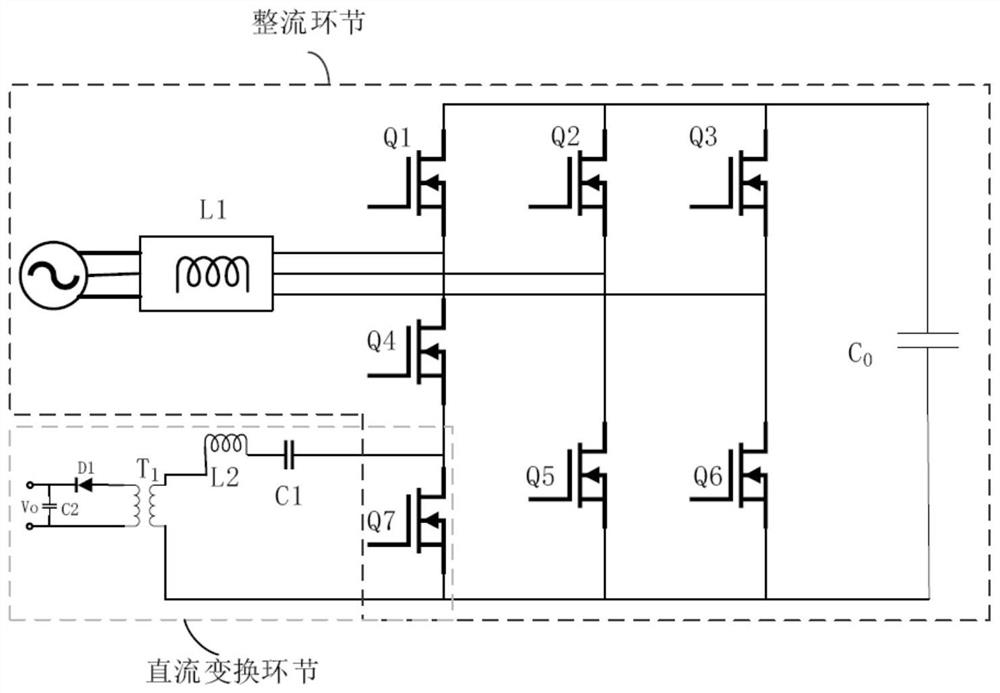
[0017] This embodiment provides a multi-switch isolated active filter circuit, which has the characteristics of fewer components and circuit isolation, and can improve the conversion efficiency of the circuit and reduce the output voltage ripple amplitude. The circuit includes a rectification link and a DC conversion link circuit, wherein the two parts of the circuit share the power element Q7. The rectification link includes AC input reactance L1, several power components Q1~Q7, capacitor C0 and so on.

[0018] The DC conversion link includes a power component Q7, an inductor L2, a capacitor C1, a high-frequency isolation transformer T1, a rectifier diode D1, and an output filter capacitor C2.

[0019] Specifically include: active filter rectification circuit, including rectification link...


PUM


Abstract

The invention discloses an active filter rectification circuit, which includes a rectification link circuit and a DC link circuit. The rectification link circuit includes an input reactance L1, a main power circuit composed of several power elements, a control circuit, and a sampling circuit. The sampling circuit The collected voltage and current data are sent to the control circuit, the control circuit outputs control signals to the main power circuit, and the alternating current is sent to the main power circuit through the input reactance L1, and the main power circuit converts the alternating current into direct current and sends it to Into the DC conversion link circuit, and output after the DC conversion link. The invention has the advantages that the topological structure design is simple, the input power factor requirement can be met, and the output voltage can be adjusted. The system is equivalent to the traditional two-stage structure, which reduces the number of components, improves the conversion efficiency, and does not require an external low-frequency isolation transformer.

Description

technical field [0001] The invention relates to the field of communication power supply, in particular to an active filter circuit. Background technique [0002] The energy source of the communication and telecommunication network lies in the communication power supply end, and its function is to provide DC and AC power. In power electronics technology, obtaining AC power from the power grid and rectifying it to obtain DC power is the most commonly used conversion scheme in communication power supplies. The role of large capacitors is to reduce the ripple output voltage. In the above scheme, only when the input voltage is greater than the output DC voltage moment, the rectifier diode will conduct, so the conduction angle of the rectifier diode is less than 100°, the input current is not a sine wave with the same waveform as the input voltage, but a serious distortion. This distorted peak pulse current contains not only the power frequency fundamental component, but also va...

Claims


Application Information

Patent Timeline
Patent Type & Authority Patents(China)
IPC IPC(8): H02M7/219H02M3/335
CPCY02B70/10
Inventor 汲克凤
Owner 汲克凤
Why Eureka
Try Eureka