Tunnel construction unit workstation

A technology for tunnel construction and workstations, applied in tunnels, tunnel linings, wellbore linings, etc., can solve the problems of long operation time, occupying large tunnel ground space, low operation efficiency, etc., and achieve efficient construction, improve work efficiency, and simple structure. Effect

Pending Publication Date: 2019-05-21
中铁工程装备集团隧道设备制造有限公司
View PDF6 Cites 5 Cited by
  • Summary
  • Abstract
  • Description
  • Claims
  • Application Information

AI Technical Summary

Problems solved by technology

[0004] The purpose of the present invention is to overcome the shortcomings of the prior art and provide a tunnel construction unit workstation, which solves the problem of occupying a large space on the tunnel floor and long working time by integrating the arch manipulator, the wet spray manipulator and the drilling assembly. Low operating efficiency and technical problems often occur in construction organization, which can meet the construction requirements of full-section excavation and bench method excavation

Method used


Image

  • Tunnel construction unit workstation
  • Tunnel construction unit workstation
  • Tunnel construction unit workstation

Examples


Embodiment 1

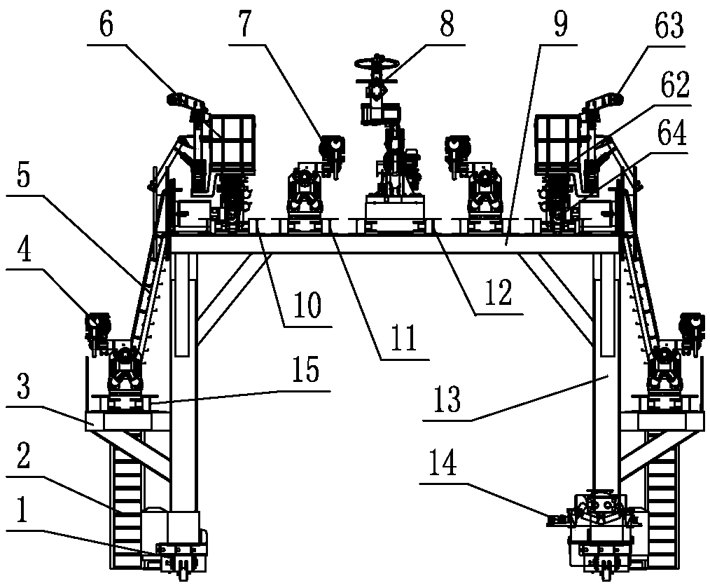
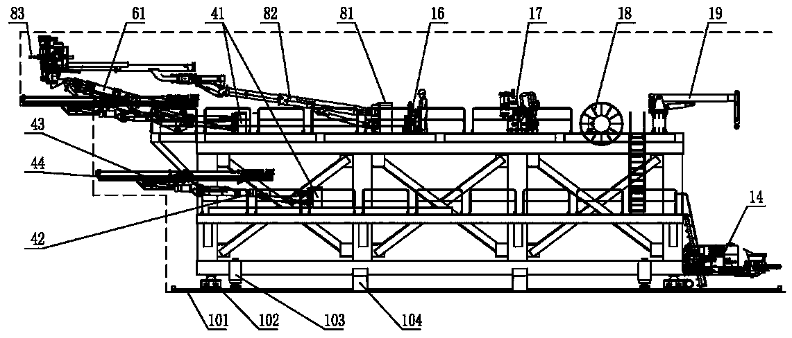
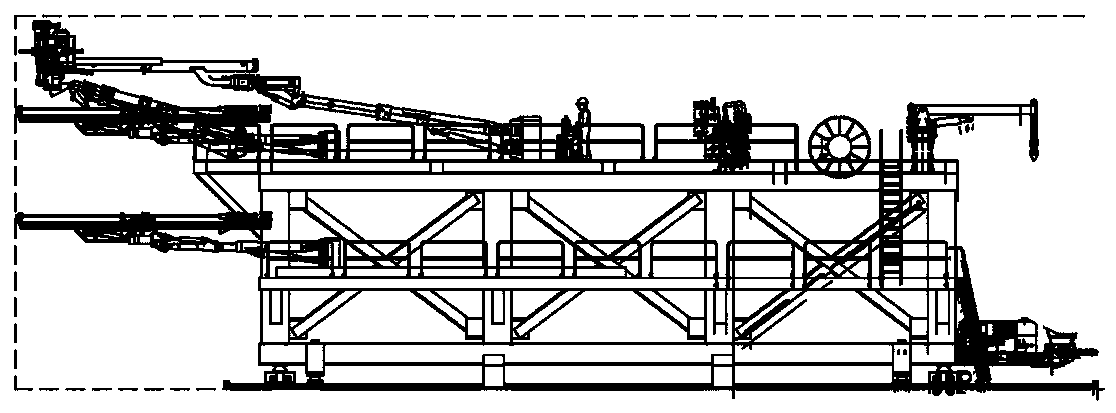
[0028] like figure 1 , figure 2 and image 3 As shown, a tunnel construction unit workstation is mainly composed of a door frame assembly and an automatic walking assembly 1 that drives the door frame assembly to move forward and backward along the tunnel. The main platform 9 is arranged on the top of the auxiliary platform 3 and the door frame 13, an escalator I2 is arranged between the auxiliary platform 3 and the ground, and an escalator II5 is arranged between the auxiliary platform 3 and the main platform 9, so that the staff can reach the platform.

[0029] Two arch chute tracks 10, one wet spray chute track 12 and two drilling chute tracks I11 are fixedly installed side by side on the front of the main platform 9, and the wet spray chute track 12 is arranged in the middle of the door frame 13 , preferably at the longitudinal center position; two arch chute tracks 10 and two drilled chute tracks I11 are respectively symmetrically arranged on both sides of the main pla...

Embodiment 2

[0041] A working station for a tunnel construction crew. The difference between this embodiment and the first embodiment is that: the arch chute track 10 is arranged on the inner side of the drilling chute track I11.

Embodiment 3

[0043] The front end surface of the main platform 9 is flush with the front end surface of the auxiliary platform 3 . Similarly, by controlling the front and rear positions of the arch manipulator 6, the wet spray manipulator 8, the drilling unit Ⅰ7 and the drilling unit Ⅱ4 on the corresponding chute tracks on the main and auxiliary platforms, the excavation by the full-section method and the step method can be satisfied. Excavation requirements, novel structure.


PUM


Abstract

The invention discloses a tunnel construction unit workstation, and relates to the technical field of tunnel construction machinery. The tunnel construction unit workstation comprises a portal assembly and an automatic walking assembly driving the portal assembly to move front and back along a tunnel, the portal assembly comprises a portal and auxiliary platforms correspondingly arranged on two sides of the portal, a main platform is arranged at the top of the portal, and an arch frame mechanical arm, a wet spraying mechanical arm and a drilling assembly are fixedly installed on the front portion of the main platform side by side. The arch frame mechanical arm, the wet spraying mechanical arm and the drilling assembly are integrated, vehicle exchange in the working period does not need towait, the circulation time can be shortened, and efficient construction is achieved. By reducing the number of trolleys, the working space can be tidied and reduced, the improvement of the working environment and the improvement of the safety are realized, and the work of deslagging and the like can be smoothly carried out. Drilling assemblies are arranged on the main platform and the auxiliary platforms, the construction requirements of full-section excavation and step-method excavation can be met, the structure is novel, and operation is convenient.

Description

technical field [0001] The invention relates to the technical field of tunnel construction machinery, in particular to a tunnel construction unit workstation suitable for drilling and blasting tunnel full-section and micro-step construction. Background technique [0002] Tunnel drilling and blasting excavation and support often require a lot of special equipment, including rock drilling jumbo, arch installation machine, concrete wet spraying manipulator, charge trolley, bolt trolley, etc. At present, one type of trolley needs to be in place for each process. Due to the limited space of the tunnel, many large-scale construction machinery are connected and coordinated in the tunnel, resulting in construction stoppage, long single-cycle operation time, low operation efficiency, and frequent problems in construction organization. [0003] As we all know, a tunnel often contains many kinds of surrounding rocks and geological conditions, and its excavation is often switched betwe...

Claims


Application Information

Patent Timeline
Patent Type & Authority Applications(China)
IPC IPC(8): E21D11/40E21D11/10E21D11/18E21D20/00E21B7/02E21B15/00
Inventor 王柏松王浩时安琪武家欣董恰王洋王松李宬曦
Owner 中铁工程装备集团隧道设备制造有限公司
Why Eureka
Try Eureka