Microwave sensor based on differential substrate integrated waveguide reentry resonant cavity and microfluidic technology

A substrate-integrated waveguide and microwave sensor technology, applied in the sensor field, can solve the problems of the microwave sensor being large in size, being easily affected by environmental factors, and being polluted by the tested product, and achieving the effects of light and thin volume, compact structure, and reduced manufacturing cost.

Pending Publication Date: 2019-05-21
SOUTHWEST UNIVERSITY
View PDF0 Cites 17 Cited by
  • Summary
  • Abstract
  • Description
  • Claims
  • Application Information

AI Technical Summary

Problems solved by technology

Traditional microwave sensors have the disadvantages of large size, low test sensitivity, easy to be affected by enviro

Method used


Image

  • Microwave sensor based on differential substrate integrated waveguide reentry resonant cavity and microfluidic technology
  • Microwave sensor based on differential substrate integrated waveguide reentry resonant cavity and microfluidic technology
  • Microwave sensor based on differential substrate integrated waveguide reentry resonant cavity and microfluidic technology

Examples


Example Embodiment

[0031] In order to better illustrate the design process and purpose, the present invention will be further described below in conjunction with embodiments and drawings:

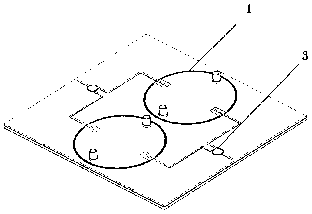
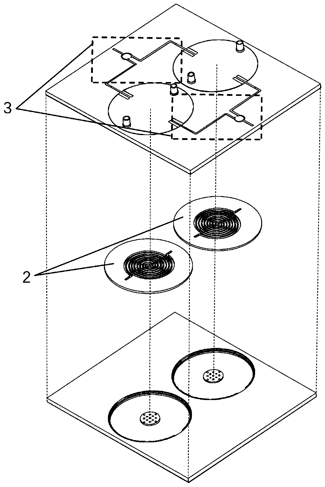
[0032] Such as figure 1 , figure 1 (A), Figure 2(a) and Figure 2(b), the microwave sensor based on the differential substrate integrated waveguide reentrant cavity and microfluidic technology proposed by the present invention includes two substrate integrated waveguide An in-type resonant cavity monomer 1, two power dividers 3, and two microfluidic chips 2 embedded in the resonant cavity monomer.

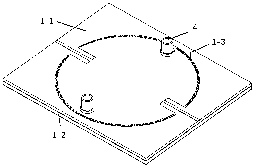
[0033] The microwave sensor is composed of an upper cover plate 1-1 and a lower bottom plate 1-2. Both the upper cover plate 1-1 and the lower bottom plate 1-2 comprise a three-layer structure, which are respectively a top metal layer, an intermediate dielectric layer and a bottom metal layer.

[0034] The bottom metal of the upper cover plate 1-1 and the top metal of the lower bottom plate 1-2 have the same area, and th...


PUM

PropertyMeasurementUnit
Widthaaaaaaaaaa
Thicknessaaaaaaaaaa
Thicknessaaaaaaaaaa

Abstract

The microwave sensor based on the differential substrate integrated waveguide reentry resonant cavity and the microfluidic technology is provided with an upper cover plate and a lower bottom plate which are overlapped, and each of the upper cover plate and the lower bottom plate comprises a top metal layer, an intermediate dielectric layer and a bottom metal layer; wherein two resonant cavity monomers are formed between the upper layer cover plate and the lower layer bottom plate side by side left and right, a microfluidic chip is embedded in each resonant cavity monomer, and the two substrateintegrated waveguide reentry resonant cavity monomers are connected in parallel and are connected in series through a power divider. According to the invention, the microfluidic chip is embedded intothe substrate integrated waveguide reentry resonant cavity based on the differential structure configuration. By utilizing the advantages of compensation of a differential structure on environmentalinterference, high concentration of a reentry resonant cavity electric field and accurate control of trace fluid by a micro-fluidic chip, the high-sensitivity high-precision sensor which is less interfered, non-invasive and easy to integrate with other planar circuits is obtained.

Description

Technical field [0001] The invention belongs to the field of sensors, and particularly relates to a microwave sensor suitable for detecting liquid media. Background technique [0002] Current microwave sensing detection methods for liquid media are usually divided into non-resonant transmission method and resonance method. Compared with non-resonant transmission method, resonant method has significant advantages such as high Q value and controllable resonance frequency. By using its resonance frequency The point shift and the phase amplitude change of the scattering parameters can realize the accurate measurement of the dielectric constant of the medium. Therefore, the detection technology scheme based on the microwave resonance mechanism has become a research hotspot and has attracted wide attention from scholars at home and abroad. [0003] However, with the continuous development of modern detection technology, the microwave sensor test system tends to be miniaturized and integ...

Claims


Application Information

Patent Timeline
IPC IPC(8): G01N22/00
Inventor 黄杰刘旭扬魏治华倪星生
Owner SOUTHWEST UNIVERSITY
Why Eureka
Try Eureka