
Head rolling machine

A head mill and roll technology, applied in the direction of roll, metal rolling, metal rolling, etc., can solve the problems of no safety protection of the roll, efficient operation of the head mill, accidents, etc., to prevent operation accidents, improve efficiency, The effect of improving quality

Inactive Publication Date: 2019-05-24
ZHEJIANG CARUITE METAL PROD CO LTD
View PDF1 Cites 3 Cited by
  • Summary
  • Abstract
  • Description
  • Claims
  • Application Information

AI Technical Summary

Problems solved by technology

However, due to the circular motion of the roll and no safety protection on the outside of the roll, when the operator is tired, it is easy for the rolling head machine to work efficiently. The centrifugal force generated by the rotating roll is always forward, and the centrifugal force will pass through the metal tube if the operator is not careful. pull towards the machine, there is a possibility of an accident

Method used

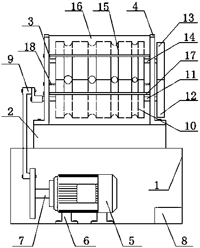
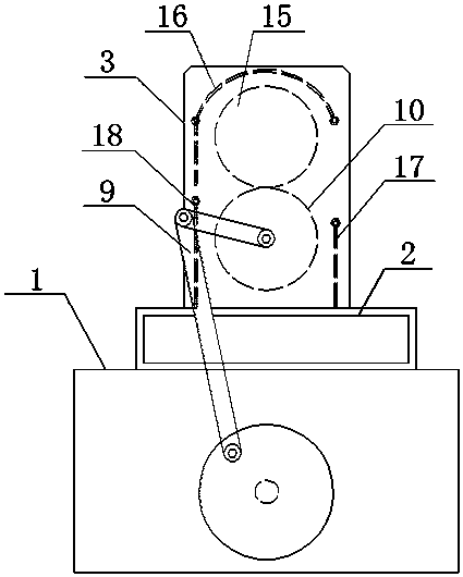

Image

  • Head rolling machine
  • Head rolling machine

Examples


Embodiment Construction

[0017] Combine below figure 1 with figure 2 Shown is a further description of a heading machine of the present invention.

[0018] A rolling head machine, comprising a motor 5, a roll 10, a roll 15, a gear 12, a gear 13 and a base 1, characterized in that: the base 1 is provided with a safety seat 2, and the safety seat 2 is provided with a left fixing seat 3 and a right fixing seat 4, the motor 5 is arranged on the base 1, the front end of the motor 5 is provided with a connecting shaft 7, and the front end of the connecting shaft 7 is provided with an eccentric crank rocker mechanism 9 The eccentric crank and rocker mechanism 9 is connected with a roll shaft 11, the end of the roll shaft 11 is provided with a gear 12, the gear 12 is connected with a gear 13 and the front end of the gear 13 is provided There are two roll shafts 14, the roll shaft one 11 and the roll shaft two 14 are respectively provided with a roll one 10 and a roll two 15 respectively. The roll shaft one 11 ...


PUM


Abstract

The invention discloses a head rolling machine, and belongs to the technical field of head rolling machine equipment. The head rolling machine comprises a motor, rollers, gears and a base. The head rolling machine is characterized in that the base is provided with a safety seat, the safety seat is provided with a left fixed seat and a right fixed seat, the motor is arranged on the base, a connecting shaft is arranged at the front end of the motor, an eccentric crank and rocker mechanism is arranged at the front end of the connecting shaft, the eccentric crank and rocker mechanism is connectedwith a roller shaft I, the tail end of the roller shaft I is provided with a gear I, the gear I is connected with a gear II, a roller shaft II is arranged at the front end of the gear II, the roller shaft I and the roller shaft II are provided with the roller I and the roller II respectively, the roller shaft I and the roller shaft II are arranged between the left fixed seat and the right fixed seat, and a machine shell I, a machine shell II and a machine shell III are arranged between the left fixed seat and the right fixed seat. According to the head rolling machine, the purposes of being reasonable in structural design, simple and convenient to operate, high in mechanical strength and safe and reliable are achieved.

Description

Technical field [0001] The invention discloses a rolling head machine, which belongs to the technical field of rolling head machine equipment. Background technique [0002] Before drawing a metal pipe, a rolling head is usually carried out, that is, the thick end of the metal pipe is rolled into a thin end. The existing rolling head method generally first heats the pipe head at high temperature, and then manually rolls it on a friction press. The labor intensity is high and the work efficiency is low. The general structure of the rolling head machines currently on the market is that the motor directly drives a roll through a connecting shaft, and the roll uses a pair of meshing gears to transmit power so that the other roll rotates in opposite directions. [0003] The publication number of the Chinese patent application is CN102671949A. The publication date of the application is September 19, 2012. The invention patent is a rolling head machine. The structure of the head machine i...

Claims


Application Information

Patent Timeline
Patent Type & Authority Applications(China)
IPC IPC(8): B21B17/14B21B33/00B21B27/02
Inventor 陈雄伟
Owner ZHEJIANG CARUITE METAL PROD CO LTD
Learn More