
Pantograph head of ring shaft rotary electric traction locomotive

An electric traction and pantograph technology, applied in the field of rail transit, can solve the problems of low utilization rate of skateboards, low utilization rate of skateboard materials, and small contact area for current, so as to improve utilization rate and service life, and improve aerodynamics. The effect of improving the stability of current flow

Pending Publication Date: 2019-05-24
SOUTHWEST JIAOTONG UNIV
View PDF0 Cites 3 Cited by
  • Summary
  • Abstract
  • Description
  • Claims
  • Application Information

AI Technical Summary

Problems solved by technology

[0004] The existing pantograph slides are in contact with the zigzag-shaped contact line to receive current. During the high-speed operation of the train, high-speed relative motion occurs between the pantograph and the catenary. As the train speed increases, the flexible contact friction between the slide plate and the contact line gradually evolves. Due to the severe rigid mechanical impact, the current receiving contact area is small and even offline arcing occurs. The arc can easily cause serious ablation damage to the skateboard, affecting the current receiving effect and service life of the public network system
At the same time, although the traditional skateboard will have lateral displacement when it is in frictional contact with the contact line, in terms of actual use, the lateral effective use area of ​​the skateboard is small, the friction does not cover the entire skateboard evenly, and the main wear is located in the "sweet spot" in the center and around the skateboard. area", resulting in low utilization of skateboard materials
The impact caused by the high-speed relative movement of the train network mainly acts on the effective use area of ​​the skateboard. Factors such as arc erosion and mechanical shock generated during the high-speed operation of the train make the effective contact area of ​​the skateboard more worn, which seriously affects the service life of the skateboard.
[0005] The existing pantograph has problems such as poor flow stability, low utilization rate of the slide plate, unsatisfactory heat dissipation effect, poor aerodynamic performance, and short service life of the slide plate.

Method used


Image

  • Pantograph head of ring shaft rotary electric traction locomotive
  • Pantograph head of ring shaft rotary electric traction locomotive
  • Pantograph head of ring shaft rotary electric traction locomotive

Examples


Embodiment Construction

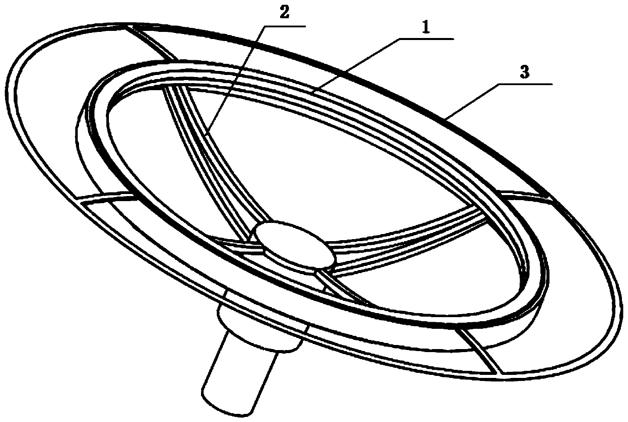
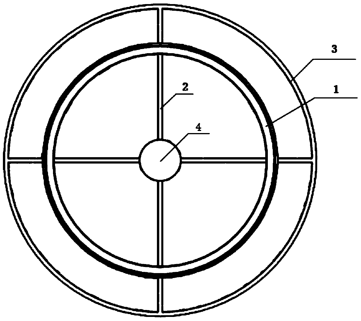
[0023] In the accompanying drawings, the part names corresponding to the reference signs are as follows:

[0024] 1—Annular skateboard, 2—Skateboard bracket, 3—Loop bracket, 4—Rotating shaft, 5—Insulation layer (that is, insulation board), 6—Screw, 7—Shell, 8—Bearing, 9—Copper sheet, 10— Electric brush, 11—spring, 12—insulating plate, 13—power transmission line, 14—contact wire.

[0025] Figure 5 Shown is a ring-shaped skateboard pantograph for an electric traction locomotive. The shell 7 fixed on the roof of the locomotive is cylindrical, the inner wall of the shell 7 is fixed with a bearing 8, and the rotating shaft 4 is installed and fixed on the inner ring of the bearing 8. Above; the bracket 2 is formed by fixing the outer ends of a plurality of radial support arms by an annular support plate; the inner ends of the plurality of radial support arms of the bracket 2 are fixed on the top of the rotating shaft 4 protruding from the casing; used as a zigzag The contact line...


PUM


Abstract

Provided is a pantograph head of a ring shaft rotary electric traction locomotive. The pantograph head of the ring shaft rotary electric traction locomotive is characterized in that an outer casing isfixed on the roof of the locomotive; a rotating shaft in a contact tube of a zigzag contact line can be rotatably mounted in the outer casing; an annular slide plate is mounted on a bracket; a plurality of power lines are arranged in the inner cavities of multiple support arms of the bracket; the outer ends of the power lines are connected with the slide plate; the inner ends of the power lines are connected with a central power line in a through hole of the rotating shaft; an annular copper sheet is fixed on the outer wall surface of the rotating shaft; a support spring between an annular electric brush and the outer casing forces the annular electric brush to attach to the annular copper sheet to generate current collection effect; the lower end of the central power line conducts currents to electrical equipment inside a vehicle body. The pantograph head of the ring shaft rotary electric traction locomotive has the advantages of enabling the slide plate to have various advantages such as high service life, large current collecting area, good stability and good heat dissipation, and being of high practical value and popularization value in the field of rail transit.

Description

technical field [0001] The invention relates to the technical field of rail transit, in particular to an annular shaft-rotating pantograph head of an electric traction locomotive. Background technique [0002] At present, most of the electric traction locomotives adopt the pantograph-catenary current receiving method, and the current receiving is realized through the sliding contact between the sliding plate of the pantograph head and the contact wire. The pantograph fixed on the roof of the electric traction locomotive has a sliding contact with the pantograph sliding plate and the catenary to receive current in the forward direction of the train; at the same time, in order to generate uniform friction between the sliding plate and the contact line, the contact line is arranged in a zigzag ( The tower pillars that pull the suspension contact line are arranged left and right along the locomotive running line), so there is still a relative reciprocating slide between the slid...

Claims


Application Information

Patent Timeline
IPC IPC(8): B60L5/20
Inventor 肖嵩罗远培张灿吴京驰饶阳
Owner SOUTHWEST JIAOTONG UNIV
Learn More