
Connection joint of double-steel-plate combined shear wall and combined floor slab connected by supporting angle steel

A technology of combined shear walls and combined floors, which is applied to floors, building components, buildings, etc., can solve the problems of small number of forms, unfavorable steel structure residences, unsuitable for double-steel combined shear walls, etc., to achieve easy construction and overall Construct simple effects

Pending Publication Date: 2019-05-24
TIANJIN UNIV
View PDF0 Cites 2 Cited by
  • Summary
  • Abstract
  • Description
  • Claims
  • Application Information

AI Technical Summary

Problems solved by technology

According to the relevant research literature at home and abroad, the number of such joint structures is small, and most of them are not suitable for the thinner double-steel composite shear wall and are not conducive to the layout of fireproof structures of steel structures.

Method used


Image

  • Connection joint of double-steel-plate combined shear wall and combined floor slab connected by supporting angle steel
  • Connection joint of double-steel-plate combined shear wall and combined floor slab connected by supporting angle steel
  • Connection joint of double-steel-plate combined shear wall and combined floor slab connected by supporting angle steel

Examples


Embodiment Construction

[0022] In order to further understand the invention content, characteristics and effects of the present invention, the following examples are given, and detailed descriptions are as follows in conjunction with the accompanying drawings:

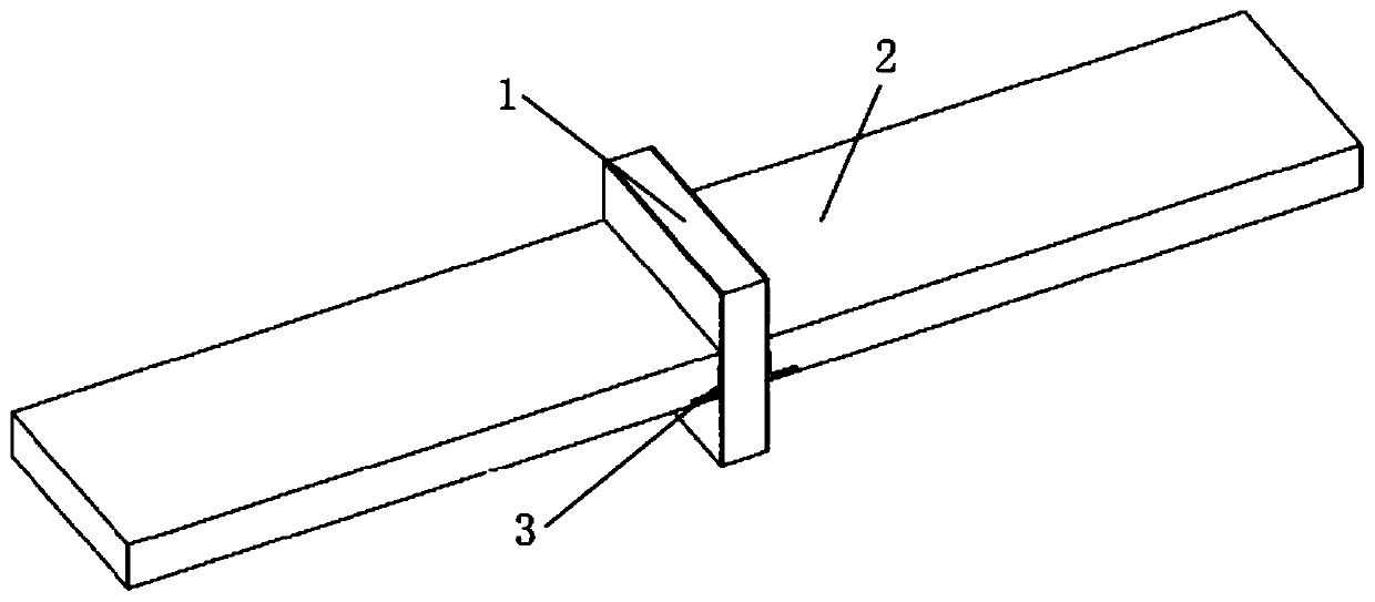
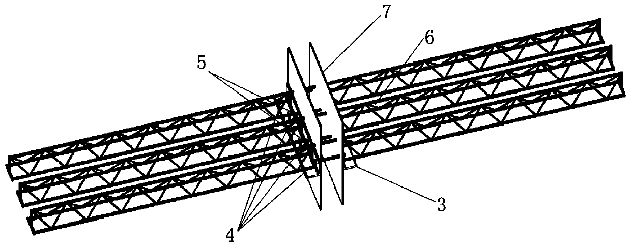
[0023] as attached Figure 1 to Figure 5 As shown, a connection node between a double-steel plate composite shear wall and a composite floor slab connected by supporting angle steel includes a double-steel composite shear wall 1 , a composite floor 2 and a supporting angle steel 3 .

[0024] The double-steel composite shear wall 1 includes two opposite steel plates 7, and the two steel plates 7 are fixed by tension bolts 4 to form a concrete pouring cavity.

[0025] The composite floor 2 includes steel bars in the floor and a steel structure main body 6, and the steel bars in the floor and the steel structure main body 6 include upper steel bars, lower steel bars and steel bar trusses, or include upper steel bars, lower steel bars, steel bar ...


PUM


Abstract

The invention discloses a connection joint of a double-steel-plate combined shear wall and a combined floor slab connected by supporting angle steel. The connection joint comprises a double-steel-plate combined shear wall, a combined floor slab and supporting angle steel arranged on both sides of the double-steel-plate combined shear wall, wherein one flange of the supporting angle steel is fixedly connected to the double-steel-plate combined shear wall and extends into the combined floor slab to be a fixing flange, and the other flange of the supporting angle steel is cantilevered and positioned at the bottom of the combined floor slab to be a cantilevered flange; upper reinforcing bars of the combined floor slab is continuous at the double-steel-plate combined shear wall and penetrate through the two steel plates; and lower steel bars or a bottom thin steel plate or a profiled steel plate of the combined floor slab is interrupted at the double-steel-plate combined shear wall and is respectively fixedly connected to the inner surfaces of the cantilevered flange of the supporting angle steel positioned on two sides of the wall. The combined floor slab is connected by the supportingangle steel, so that the performance of the double-steel-plate combined shear wall is complete, and joint domains are stressed together; and the structure is simple, the force transmission path is clear, and the assembly trend is met.

Description

technical field [0001] The invention relates to construction engineering, in particular to a connection node between a double steel plate combined shear wall and a combined floor slab connected by supporting angle steel, when the double steel plate combined shear wall is connected to the combined floor, the floor is supported by a flange of the supporting angle steel , the other flange is closely connected with the shear wall, which is a new type of wall-slab connection node form that transmits the force of the floor. Background technique [0002] At present, a number of national policies have been issued to vigorously develop prefabricated steel structure buildings. Among them, the double-steel composite shear wall has been gradually popularized and used as a lateral force-resistant component of high-rise steel structure residences due to its high bearing capacity. The double-steel composite shear wall that is common in engineering does not interrupt the overall structure,...

Claims


Application Information

Patent Timeline
Patent Type & Authority Applications(China)
IPC IPC(8): E04B1/61E04B5/29
Inventor 周婷刘映良陈志华陈华周张鹏飞张相勇李凌峰
Owner TIANJIN UNIV
Learn More